On the resistor, most any size wattage is fine 1/4W is typically easy to find and cheap. I'd also like a 100K resistor as well. We are going to check the capacitors. We can't easily check the ESR ( Effective Series Resistance ) but we can check to see if they are dried out. I'm relatively sure your meter has a typical 1M input resistance. We will use that to make crude measurements of the filter capacitors that are suspicious for being out of tolerance ( I wish you'd got the resistor when I'd asked for it. It wasn't an idle request ).
We will be measuring the time constant of the capacitors. Any that are way off will need to be replaced.
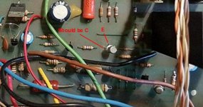
To do this, we'll need to remove them from the board. Electrolytics are polarized. If we apply the voltage to them backwards, it will quickly destroy them ( If using a power supply it will be a small explosion ). Please be careful to observe the polarity of the capacitors when testing and installing back on the board. It looks as though the capacitors are what is called radial lead ( upright can types ). Most of these mark the negative side by a stripe with a dash on it. A few are known to mark the positive side, also with a stripe, down the side, but a + sign instead. Mark the board with the polarity indicator as we do these so that there is no mistake them when reinstalling them.
We have two that we can test right away with the meter you have, using the 5V of the logic board. While testing these, we should disconnect the power transformer from the analog video board so we don't have to worry about it. I believe, from some pictures, the transformer can be disconnected with a connector.
The capacitors C3 and C13 can be tested with the meter and the 5V. So lets do that while we wait for other stuff to come in.
What we'll be doing is measuring how fast the capacitors charge up. The typical specification of these is +20% -10%. So for C3 and C13 that is suppose to be a 47uf, normal range is about 56uf down to 42uf. Anything much under 40uf and we'll want to replace it. These can also be excessively leaky as well. If they seem to be taking a really long time to charge, this would indicate that they are excessively leaky. In normal use, they do leak a tiny amount but excess leakage is an issue.
We'll use the calculated time constants for these. Remove the capacitors one at a time and test them.
Here is a table of time constants. These are to .63*V for one time constant but we will use 1/2 voltage time of 0.7 time constants for simplicity.
If we use 5V, that means the voltage will be 2.5V. Since we are going to connect the meter in series with the capacitor, it will be 2.5V on the meter and 2.5V on the capacitor ( 2.5 + 2.5 = 5 ).
Here is the table we'll work with:
Time to 1/2 voltage of 2.5V using 5V source.
Capacitance, resistance, minimum time, maximum time
47uf, 1Meg( meter ), 30sec, 36sec
470uf, 90K ( 100K parallel to meter ), 27sec, 32sec
220uf, 90k, 12.5sec, 16sec
4700uf, 10K, 30sec, 36sec ( we'll put the resistor in parallel with the meter again but the error is small enough that we can ignore it )
This will be done always with the meter and paralleled resistor in series with the capacitor. The negative end of the capacitor connected to the logic ground and the other end of the meter/resistor to the +5V. We can start the timing by momentarily shorting across the capacitor. The meter will then start measure 5V. As the capacitor charges, the meter's voltage will gradually drop to 2.5V ( we hope ). When it reaches 2.5V, we'll note the time by watching a clock.
There are a number of smaller capacitors that we will not be able to measure this way. If we see significant failures on these bigger capacitors it may be worth replacing them as well.
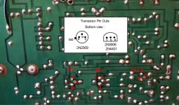
Anyway, we can do the 47uf caps while waiting on other parts. There are some test we can do on Q11 to Q13 but lets deal with the capacitors first.
Anything you are not sure about, ask questions.
Dwight