• Please review our updated Terms and Rules here

PETunia's Repair Log

This is indicating .75V of noise. This seems way to much for TTL if it is real. Where was your scope return for these measurements?
I was using Pin 22 of one the empty 6550 sockets. I did wonder 750mV is quite some ripple.

I will try that other ROM test... looks good.
 
Isn't that like asking a lady her age; I would never divulge. I did buy it on eBay earlier in the year... so you could search the sold listings.

Well thats an absurd answer. I paid $275 for mine which was broken. And why would i search the sold listings when i can easily ask you directly? Whats the big deal with saying how much you paid????
 
Good spot about the pk-pk noise Dave - I missed that...

So, there is nothing fundamental wrong if you can get someone else's PETTESTER to work. We just have to smoke out the metal mouse...

Dave
 
OK... I burnt the PETTESTER into something I could put in H3.... and put the original MOS / MPS 6540 / 018 4478A aka rom-1-f800.901439-07.bin back into H7.
I have just I1/I2 and J1/J2 populated with 6550s
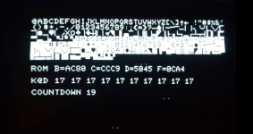
and turned on...
FirstScreen.png
ROM B is changing... not unsurprising since I think that part of the memory map is unpopulated?
I am a bit uncertain about the ROM F checksum.... I am pretty sure the F000 ROM contains... rom-1-f000.901439-04.bin and F800 ROM contains... rom-1-f800.901439-07.bin; if I take those two .bin files and combine them and then put the 4K result into HxD I get
Checksum-16: 0CA4 which is what appears on the screen?
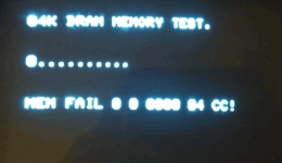
after a while it goes to...
Capture2.PNG
which although not very clear says MEM FAIL 0 0 0800 04 CC
which I think means $0800 = 2k; and given I have 4x 1k x 4bit is about right.
The PDF suggested their was a previous screen.... I didn't see it! On the first screen I saw in the KBD section which actually displayed as K@D the numbers were 17s.... I tried pressing keys.. but they stayed at 17s.

On the subject of voltage rail ripple... does that suggest a bad main filter cap? Should I replace it? with?
 
Last edited:
OK... I burnt the PETTESTER into something I could put in H3.... and put the original MOS / MPS 6540 / 018 4478A aka rom-1-f800.901439-07.bin back into H7.
I have just I1/I2 and J1/J2 populated with 6550s


ROM B is changing... not unsurprising since I think that part of the memory map is unpopulated?

Good info, yes ROM at $B000 is empty. Key board is controlled by PIA #1 at G8. Is it in place or removed during this test?

which although not very clear says MEM FAIL 0 0 0800 04 CC
which I think means $0800 = 2k; and given I have 4x 1k x 4bit is about right.

On the subject of voltage rail ripple... does that suggest a bad main filter cap? Should I replace it? with?

Yes it passed up to $0800 of RAM which is all you have installed at this time. All OK with RAM.

As far as filter cap, you may have to make an AC voltage measurement to find out. The +5 V regulator should have handled a modest amount of ripple as its input is +9 VDC unregulated.

With good ROM and $800 of good low RAM, it should have gone further in boot sequence, strange.
 
Key board is controlled by PIA #1 at G8. Is it in place or removed during this test?
I checked and G8 was not present! Sorry been playing the Hokey Cokey with chips recently... anyway B8 was fitted but G8 was out.
I populated G8 and the Keyboard reports 00 00 00... 00 etc... and pressing a key shows a number e.g 02 or 04 somewhere... looks hopeful.
I then swapped G8 and B8 (I think G8 faces left marked 40 on the board... B8 I think faces right)... but this produces Kbd D7 D7..... D7 and if wobble the chip I can get FFs and D6s and other combinations. So either that PIA is bad or maybe crusty pins.

Oh... and with the monitor warmed up the initial screens show up as described in the manual... that looks OK.
 
Last edited:
You are under no obligation in this forum to quote the price you paid although I would have told him $50 at a flea market and it would have made him cry!
-Dave
 
Yes, the initial page appears to have some extraneous ".." and "K@B" which is clearly wrong. However, the initial tests (which passed) checked out the video RAM - so the errors are probably 'video output' related.

The assumption is a minimum PET with 4K - so if you only have 2K of RAM installed then the first memory test it tries would fail (as identified). I would suggest adding the other RAM devices at some point and running the exhaustive memory tests for a while...

Some of the screens will only stop if they detect an error. In my view, if the software doesn't detect any errors, it just carries on. The problem I have is one of assuming the keyboard interface works (if I wait for a keypress) and then I have the problem of the different key mappings for the various flavours of PET, keyboard type and internationalisation. Only one key (the RUN/STOP key) is common to all keyboards! OK, I could use the RUN/STOP key...

You are very close - so there must be either a power supply related issue, a bad contact or an intermittent ROM/RAM causing your problems.

Dave
 
I am a bit uncertain about the ROM F checksum.... I am pretty sure the F000 ROM contains... rom-1-f000.901439-04.bin and F800 ROM contains... rom-1-f800.901439-07.bin; if I take those two .bin files and combine them and then put the 4K result into HxD I get
Checksum-16: 0CA4 which is what appears on the screen?

You are correct. The two checksums from sockets H4 and H7 will add up to the 4K checksum for the $F000-FFFF address range and will equal $0CA4. Sorry for treating you like a beginner, now I know you are a computer man.

What is the AC Volts reading across the power connector J8-pin 2 (+9 V unregulated) and J8-pin 3 (ground)? We would expect to see some AC. I will check on my 8032 PET for a comparison.
 
I checked the numbers and the correct sum for BASIC 1 for the $F000-FFFF range seems to be 0CA4 so your ROMs are correct, and the manual must be in error.

Note to daver2: our man has caught a typo in Pettest manual. Error in table listing sumcheck of BASIC 1 $FXXX was 0CD4 and should be 0CA4.

I used zimmer data and cross checked with MikeS data.
 
Using a digital DVM, with the black probe clipped on the big cap C1 (23K uF) negative (blk wire) and the red probe in J8- pin 2, I get 0.125 VAC and 10 VDC with system connected.

Looking at typical Vcc pins, I get 0.003 VAC and 5.1 VDC. This is on a 8032 PET.

With your readings, there is something amiss. But first, with power off, measure the resistance between chassis and digital ground, perhaps you have some bad connections.
 
I would check the AC reading with a capacitor to isolate the DC path. Not all meters will read AC properly with a DC bias. A 1 or .1uf should be enough isolation for an AC reading with a typical DVM having 1Meg input resistance.
Dwight
 
Hi Dwight,
Nice to hear from you on the 'The Commodore Channel'. I see your postings on the other forums. My 3 mV AC reading of the Vcc bus seems too good to believe. I think my DVM measure volts peak not RMS. Will that contribute an error with a DC bias? I was going to try with an old VOM, but forgot.
-Dave
 
So the on page 10 of https://drive.google.com/drive/folders/1fyLbr1kcG98a2FDOMo1H5pj9lIdJpHcx?sort=13&direction=a the value needs tweaking?

I'm thinking power supply issues at the moment... might try some more detailed investigation.

Just to confirm, the checksums I obtained were using the Zimmers images with VICE running my PETTESTER in the EDIT ROM socket. It is possible that I mistyped the checksum into the manual. VICE also does a few automatic modifications to the Kernal ROM. I thought I switched all of these ‘improvements’ OFF, but I may have missed one of course. VICE may also ignore me!

Or you potentially have a BAD Kernel ROM half (as Dave says).

Dave
 
Hi Dwight,
Nice to hear from you on the 'The Commodore Channel'. I see your postings on the other forums. My 3 mV AC reading of the Vcc bus seems too good to believe. I think my DVM measure volts peak not RMS. Will that contribute an error with a DC bias? I was going to try with an old VOM, but forgot.
-Dave

Many VOMs are even worse. They just rectify the voltage with a bridge using copper oxide diodes. You connect 5 volts DC to a VOM and you are likely to read about 3 or 4 volts on an AC scale. As for your DVM, there are spikes higher than 3 mv but it is possible that it is just too high a frequency to indicate much. The large reading seen on the other is way too much if it is really not just an artifact of the meter with a DC voltage. Using a capacitor to isolate is the best way on any meter. On a VOM with typical 20K per volt will need a larger capacitor. I would hope that almost everyone would have a 1 or 0.1 uf capacitor laying around in their junk drawer, even if they just removed one from some old board that they don't care about.
The best way, and right way, is to use an oscilloscope. It is important to also look at the ripple. If it is 60Hz, it means you have a failed rectifier. If it is 120Hz, it means it is likely a bad filter capacitor. You can tell that from a DVM. Over course, without knowing the load, it might even be some capacitor on the board trying to fail or a bad regulator.
I had a N* with a weak regulator that had about as much ripple on the output as on the input, although, it was clipping at 12V. Again, from the scope, I could see that it had more than enough over voltage on the input. It was just shot.
Before I'd trust any AC reading on a meter, I'd want to know it was isolated from DC bias.
Dwight
 
His Dwight,
Excellent tutorial. I forgot that simple voltmeters only rectify AC signals to drive the meter movement. On my VOM there is an 'Out' jack in addition to the '+' and '-' jacks. Does that jack insert a capacitor in the circuit? Can that be used to remove DC bias voltage?
 
Back
Top