• Please review our updated Terms and Rules here

Playing with HP Digital Signatures on a PET 2001

Nivag Swerdna

Veteran Member
Joined
Jul 17, 2020
Messages
740
Location
London, UK
I recently discovered the joy of HP Digital Signatures, i.e. to monitor a digital signal during a period of time and to generate a 'checksum' of the data in between as a way of characterising the signal you just observed. For microcomputer systems a good test set-up is to install a NOP adapter, use A15 as the start and stop signal (i.e. define the measurement period to be one cycle of A15) and then measure another pin.

Now HP Signature Analyzers may have been the rage some decades ago but are now pretty rare so I set about devising a couple of methods of generating signatures.

CaptureHPSig.PNG

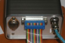
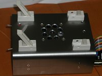
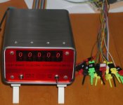
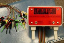
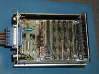
The first was used here... I have a small microprocessor on a board that fits in the CPU socket and can twiddle all the pins. There is a flying lead which can wander around other pins under test and the result is sent back to the PC.

HP's signatures are quite clever! e.g. the signature of address line A6 is U759. As you wander around the board if you find another pin that has signature U759 then you can be pretty confident you have A6!


CaptureCheckup.PNG

Has anyone tried this technique on their PET?

With a NOP adapter it is possible to verify all the address decoding logic (for Reads anyway) very rapidly.

Would you like to compare your results to what I have in the attachment?

Thanks for your interest!

PS

sigrok does support HP Signatures so if you have a cheapo logic analyser then you can probably produce signatures too (although it is a bit fiddly since you need to capture and then analyse rather than getting realtime results)
 

Attachments

  • PET 2001 HP Signatures.pdf
    68.4 KB · Views: 6
Last edited:
That's neat - not seen those before!

Have you come across these https://huntron.com/products/trackers.htm?

They test for faults with the power off! Seriously. Unfortunately, you need a working reference machine to characterise the measurement points.

Our contract partners still use these to repair certain cards for us at work.

Dave
 
Actually, it is quite simple...

You put the red and black probes on two points of the unpowered reference board and it will give you a curve based upon the circuit elements (resistance, inductance and capacitance) between the two probes. This can be stored into a library.

You can construct a board test based upon multiple measurements. You can enter text for the operator to put the probes on specific points of the PCBA under test.

From this, you can 'gauge' where a test board differs from the reference board.

The advantage is that the tester can test voltage regulators, passives and analogue components as well as digital - all without being powered or knowing the function of the circuit.

Of course, the more expensive units have large front-end multiplexers so that you can connect multiple probes (more commonly via IC clips) to automate the process. You then use the human operator as a cheap means of moving the probes under instruction from the computer. Sounds like the future to me!

This is a similar process to checking for counterfeit parts. In this you connect all of the part pins to GND except for one pin and you characterise the internals between the selected pin and GND. You perform the same test for all other pins on the package. This gives you an overall characterisation for each pin of the IC.

Dave
 
Here's one of the same measurements made with a real antique...

CaptureHP1.PNG

Real 6502 on a NOP adapter which breaks out A15, phi2, GND etc.

and

CaptureHP2.PNG

P7AA reassuringly matches what I would expect on p3 of H3... i.e. this is nSELE
 
Last edited:
Interesting signature tool.

In a similar way I wanted to know the binary values of an up to 16 bit data or address line at any moment in time. So since that messes with my head in binary, I initially thought to simply display those as HEX using 4 of the the famous TIL311 displays which have latches. But then I thought, it would be great to see the value in decimal.

I built a type of "logic probe" that has 16 input buffers and an array IC's (the now rare part ; the TI SN74185A Binary to BCD IC) takes 16 of those and used the TIL 311 too, 5 of those.

I built the unit into a high quality Takachi extruded aluminium enclosure, it uses an original LM309k National gold plated voltage regulator and it runs from an external 9v wall wart, I had a pcb made for it.It has tilt feet (a Takachi option for enclosures) and uses a DIN connector for the probe cable, which is a ribbon type (sorry about the blurry photos). It required a small fan for ventilation as collectively the 74185's dissipate a moderate amount of heat. No electrolytic caps used, Axial mil-spec tants instead.

In any case I think that all equipment should not only be electrically good but be physically well constructed, so I'm obsessed with a quality build. All the hardware is stainless steel and the basic infrastructure is supported by two 10 x10mm cross section aluminium bars, that I machined to go between the front & rear panels, so the case comes off the assembly like a clam shell. Often I use 4 of these bars for larger Takachi enclosures and call the construction method the "Endoskeleton Technique" as I used on the Amber VDU project.

The unit also has a logic level Latch input to freeze the current number, displayed in decimal. It also has a manual freeze or latch switch. The delay time from receiving the binary data and displaying it, is only 350nS .

So I use this as a type of logic probe. I have test clips which clip onto DIL IC's to make easy connections to the data or address lines to be monitored/tested. If any of the more significant lines are not connected the are seen as low because of the way I configured the buffers, which are cmos and have tie resistors (resistor arrays seen on the pcb). So the unit has a high-Z input and doesn't bother the logic circuits it is connected to.
 

Attachments

  • bindec7.jpg
    bindec7.jpg
    195.4 KB · Views: 5
  • bindec6.jpg
    bindec6.jpg
    240.8 KB · Views: 6
  • bindec5.jpg
    bindec5.jpg
    226.1 KB · Views: 5
  • bindec4.jpg
    bindec4.jpg
    146.1 KB · Views: 4
  • BINARYDEC3.jpg
    BINARYDEC3.jpg
    175.2 KB · Views: 6
  • BINARYDEC2.jpg
    BINARYDEC2.jpg
    780.3 KB · Views: 7
Last edited:
Introducing my latest gadget... although I don't think I can sell them until the chip shortage calms down...

Brand new for 2022... HP Signature Analyser...

CaptureSig1.PNG

and

CaptureS2.PNG

Any interest?
 
Although if you are driving the 7 segment displays directly, why don't you use a-f rather than the letters that HP used?

Dave
 
We used to have a Schlumberger S635 in circuit tester that allowed logic IC's to be tested in circuit with the power off. Each chip could be clipped onto and it would run the checks. Worked ok but never really got used to its full potential.
 
Although if you are driving the 7 segment displays directly, why don't you use a-f rather than the letters that HP used?
The use of the characters was an intentional design decision by HP to signify that the binary value is not significant; I follow the same logic to remain compatible with existing analysers. The signature is not a simple count.
 
Huntron Trackers are great! I used them years ago in the Marine Corps when I worked on ATC Radar systems.

Tom
Huntron trackers have the advantage of testing unpowered boards & components. The only thing with these is that it often pays to have a good board for a reference and although they can give an input an output pin signature on an IC they won't detect a failed IC when the failure is in intermediate circuitry inside the IC, which can often be the case, especially as the IC's internal die complexity increases and there are more intermediate stages. So they can miss a defective IC, the only way to find that being to run the board powered. However, for discrete transistor circuitry they don't have this issue. This is probably why, as time went by, the Huntron did not revolutionize the electronics service industry, since IC's came to dominate designs and discrete circuitry diminished in popularity.
 
Nivag, that is a very nice board you made. Which is the hard to get IC ?

I have been hearing more and more lately about hard to get IC's. A number of projects done by Silicon Chip magazine are now suffering from unavailable IC's, and not vintage IC's either, relatively new ones.

Ironically vintage IC's of most types are much easier to get. It might get to the point where we will have to go back to 74 series logic to guarantee supply, which won't bother me much because they are my favorites !

Recently I built a Tic Tac Toe computer. In this case, only a few months after making it, the modern Ratiometric Hall sensors I used became unavailable, like many new IC's. But, all of the 74 series IC's are still available as is the vintage Winbond version EEPROM of the ROM:

 
Last edited:
Yes, we are having supply chain hell at the moment. Even some 'vintage' parts are difficult to get hold of in quantity.

I suspect fabs are building silicon to order for the largest profit. We have been trying to get hold of a new digital audio mixer desk for Church and TDK DC to DC converters for work - nightmare!

But, if you want to buy any number of iMacs, absolutely no problem...

Dave
 
HP were the pioneers of logic analysis. Here is a really nice write up. I don't have a signature analyzer, but I've got a 1600A LSA, which is about to get a permanent place on my bench once I've given it a thorough check over to identify and fix any faults it might have.

1657582009424.png
 
Last edited:
Back
Top