• Please review our updated Terms and Rules here

Starting my first Pet, a 4032 in desperate need of some love

Mike Brixius

Experienced Member
Joined
Nov 5, 2022
Messages
134
Location
Springfield Oregon
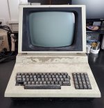
This machine came to me from a friend and my plan is for a full restoration. Since this is my first pet (And first post here after lurking for ages) I thought I should lay out my battle plan and see what the experts suggest

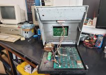
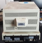
It came from the Alameda Unified School District in California and has been in storage for decades. The outside is not terrible barring the missing label and some broken keys (I have the label and a key coming but will have to find parts to repair some others)
4032 on Bench 2 - Copy.jpg
Back 1 - Copy.jpg
Bottom of VDU 3.jpg

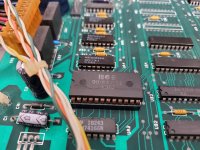
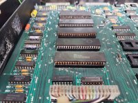
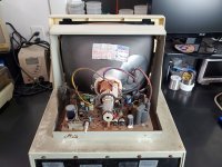
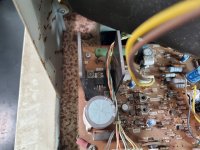
Inside there is a LOT of rust so I'll skip the smoke test and go straight to restoration.
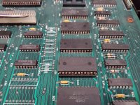
Board 7.jpg
Ugly Chip Pins 4.jpg
Ugly Chip Pins 5.jpg
Inside Monitor 1.jpg
Inside Monitor 8.jpg
Inside Monitor 13.jpg
The battle plan...
Run the board through an ultrasonic cleaner (I think it will fit in 2 passes).
Remove all the socketed chips and clean with a scratch pen.
Remove any corroded chips so they can be cleaned and socket them.
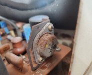
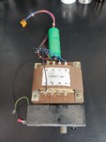
Clean and test the transformer and coat it to prevent further rust.
Replace the rusty VR... Or
I usually try to keep as original as possible but on this one I am leaning towards just replacing the Electrolytic caps, Bridge Diodes and Voltage regulators
Reform the large cap.
Clean the case and remove rust then either touch up or repaint depending on how it is looking
Clean and recap the VDU board
Clean the keyboard but hold off on conductive paint until I see if it works
Reassemble and start troubleshooting (1000 tiny cuts?)

I have a ROMulator on order but I am guessing that this project will just be getting started with the above

To me it looks doable but will definitely require a few level ups for me.
 
Well, you've come to the right place!

Don't forget to add your location to your profile. You will also be moderated for the first 10 posts.

Which ROMulator have you purchaesed?

Two of them have inbuilt NOP generators and my PETTESTER - some others don't.

What part number is etched on the main PCB? SO we can identify the correct schematic.

Dave
 
Forget about all the nonsense you see on you tube videos about "safely discharging a CRT" to work on most VDU's.

It is all a load of complete nonsense, by people who were frightened of sparks (plasmas) when a CRT's anode connections were discharged and they didn't understand about the designs of CRT guns and that the stored charge in the CRT was completely isolated from the base pins (socket) pins of the CRT's gun assembly. Also they didn't bother to calculate the stored energy either. So they jumped to conclusions about the dangers of working on CRT based VDU's and the requirement to discharge them, for "safety".

The charge stored on the bulb of a CRT after the VDU is turned off, is very safely stored there. The external and internal Aquadag (conductive coating) of the CRT are the "plates of the capacitor" that store the charge and the glass bulb of the CRT is the dielectric. The only way you can connect yourself to the internal Aquadag is to go under the anode cap and touch the anode connection, which is connected to the internal Aquadag. You don't need to go under there for general VDU servicing anyway.

This stored charge is completely isolated from the CRT's base pins (the CRT's socket connection).

So with the set turned off you can happily work on the VDU. You cannot come into contact with the stored charge ...unless you go under the anode cap (EHT cap) and touch the anode connection that is connected to the internal Aquadag.

For most repairs this is not necessary to venture under the anode cap. Plus, even if you did go under there, the stored energy on the PET's CRT's is less than 100mJ, it will be a similar zap to what you get if you touched a lawnmower or car's spark plug terminal, for one spark, and not risky to your health, unless perhaps you had a pacemaker or implantable defibrillator.

Also, if you can wait 12 to 24Hrs, before you go under the anode cap, say if you need to remove the CRT or the LOPT (line output transformer), the charge has depleted anyway, because the Silicon EHT rectifier has a non zero reverse leakage.

I can hardly believe the nonsense that is on youtube video's about the need to discharge CRT's before working on VDU's. And the instructors show the discharge spark, to make it look impressive and that they have saved you from certain doom. It all reminds me of the remark Sigourney Weaver made in one of the Alien movies : "Did IQ's drop sharply while I was away"

There is only one sensible reason to discharge the CRT if you are not prepared to wait 12 to 24 hrs for it to self discharge, via the EHT rectifier's non zero reverse leakage current:

If you are removing a CRT from a VDU, in short order after you de-power it, and it has not been discharged and you are carrying it across a room, if you come into contact with the anode connection and there is still some charge there, the muscle twitch it induces in your hand and arm could cause you to drop the CRT on the floor.

If you are in a real hurry and you want to discharge the CRT's anode, the better way to do it, rather than a direct short with a wire, it is better to simply to use an EHT voltage measuring probe as a tool to do the discharge. These have a very high input resistance of 100M Ohm to 1G Ohm (depending on the probe design) and make for a gentle discharge.

You could ignore the Physics if you like, but if you discharge a 500pF capacitor (typical capacitance of the tube in a 9" PET VDU) , charged to 10kV into a dead short of a conductor, like a wire link, the peak initial currents are extremely high and that is not good for the region inside the CRT where the internal Aquadag coating is connected to the final anode metal button connection, that passes through the CRT's glass wall.
 
Last edited:
Well, you've come to the right place!

Don't forget to add your location to your profile. You will also be moderated for the first 10 posts.
I am in Springfield Oregon. I added that to my profile as well as a link to the about me page on my Blog to avoid having to write too much copy :)

Which ROMulator have you purchaesed?

Two of them have inbuilt NOP generators and my PETTESTER - some others don't.
Doh, I was not aware there was more than one. I ordered it from https://bitfixer.com/product/romulator/

What part number is etched on the main PCB? SO we can identify the correct schematic.
The number on the board is 8032089. I'm glad you asked, I was thinking it was 8032090 based on the layout in the Tech manual.

 
Forget about all the nonsense you see on you tube videos about "safely discharging a CRT" to work on most VDU's.

It is all a load of complete nonsense, by people who were frightened of sparks (plasmas) when a CRT's anode connections were discharged and they didn't understand about the designs of CRT guns and that the stored charge in the CRT was completely isolated from the base pins (socket) pins of the CRT's gun assembly. Also they didn't bother to calculate the stored energy either. So they jumped to conclusions about the dangers of working on CRT based VDU's and the requirement to discharge them, for "safety".

The charge stored on the bulb of a CRT after the VDU is turned off, is very safely stored there. The external and internal Aquadag (conductive coating) of the CRT are the "plates of the capacitor" that store the charge and the glass bulb of the CRT is the dielectric. The only way you can connect yourself to the internal Aquadag is to go under the anode cap and touch the anode connection, which is connected to the internal Aquadag. You don't need to go under there for general VDU servicing anyway.

This stored charge is completely isolated from the CRT's base pins (the CRT's socket connection).

So with the set turned off you can happily work on the VDU. You cannot come into contact with the stored charge ...unless you go under the anode cap (EHT cap) and touch the anode connection that is connected to the internal Aquadag.

For most repairs this is not necessary to venture under the anode cap. Plus, even if you did go under there, the stored energy on the PET's CRT's is less than 100mJ, it will be a similar zap to what you get if you touched a lawnmower or car's spark plug terminal, for one spark, and not risky to your health, unless perhaps you had a pacemaker or implantable defibrillator.

Also, if you can wait 12 to 24Hrs, before you go under the anode cap, say if you need to remove the CRT or the LOPT (line output transformer), the charge has depleted anyway, because the Silicon EHT rectifier has a non zero reverse leakage.

I can hardly believe the nonsense that is on youtube video's about the need to discharge CRT's before working on VDU's. And the instructors show the discharge spark, to make it look impressive and that they have saved you from certain doom. It all reminds me of the remark Sigourney Weaver made in one of the Alien movies : "Did IQ's drop sharply while I was away"

There is only one sensible reason to discharge the CRT if you are not prepared to wait 12 to 24 hrs for it to self discharge, via the EHT rectifier's non zero reverse leakage current:

If you are removing a CRT from a VDU, in short order after you de-power it, and it has not been discharged and you are carrying it across a room, if you come into contact with the anode connection and there is still some charge there, the muscle twitch it induces in your hand and arm could cause you to drop the CRT on the floor.

If you are in a real hurry and you want to discharge the CRT's anode, the better way to do it, rather than a direct short with a wire, it is better to simply to use an EHT voltage measuring probe as a tool to do the discharge. These have a very high input resistance of 100M Ohm to 1G Ohm (depending on the probe design) and make for a gentle discharge.

You could ignore the Physics if you like, but if you discharge a 500pF capacitor (typical capacitance of the tube in a 9" PET VDU) , charged to 10kV into a dead short of a conductor, like a wire link, the peak initial currents are extremely high and that is not good for the region inside the CRT where the internal Aquadag coating is connected to the final anode metal button connection, that passes through the CRT's glass wall.
Hugo

I think you will find that the source of this information is because back in the day, large color TV consoles could store a substantial charge that could put a person with a heart defect (diagnosed or not) at risk. Combine that with the need to keep things simple for the general public it was boiled down to NEVER MESS WITH IT. This is something I learned early since it was my job, from about 12 years old on-wards, to pull the tubes and take them to the store and test them every time the TV died (Which was often since it was an aged hand me down from my grandparents)

This is a safety measure that was also taught to me in college and that I taught when I covered the local community colleges night classes for a year and, as I am sure you know, old habits die hard! (Also, to be clear, this was in the late 80s so my old electronics chops are VERY rusty. Always feel free to correct me when I am wrong!)
Personally, I still discharge the CRT any time I am going to remove the anode cap, not because I am afraid for my health, I just don't like electric shocks! That said I do agree that a 12" monochrome CRT is not going to cause any serious harm. I do let the machine set for an hour or more so that any internal resistance will have already dissipated the charge so I have never actually had any "snap".
 
I realized I should give some background on myself so you know my skill level. It used to be a lot higher than it is now :) but It's gradually coming back to me!

I have a 2 year degree as an electrical engineering tech (So design, not repair). I also taught the 1st year electronics night classes at the local community college for 1 year to cover when the instructor fell ill just after I completed the program (Analog Electronics 1-3, Digital Electronics 1-3, and Lab Practices). This was in 1990 and I ended up spending 1995-2020 running a business so these skills are largely lost to me. It's funny how much you can forget in 25 years! I was always much stronger on the digital side so I still do fine there but throw a switching supply or a monitor at my and I struggle.

I have been working on restorations since 2020 and can probably repair a C64 in my sleep but have never worked on a Pet. The hardware design work I did back in the day was mostly Amiga based with a little 6502 and 8088 thrown in.

Tools wise I have a meter (Brymen BM235) and Oscilloscope (Siglent 1104X-E). Honestly I barely use the scope because I find the menu driven interface annoying after my old Tektronics scope in the 80s. I know, I need to take the time to learn it! I also have a Tektronics 453A but its a bit large for my bench and, at about 50 years old, is probably not up to daily use. It does seem to work looking at data and address lines on a C64 but there is no signal on the calibration rail so it clearly is not 100%.

Beyond that I have all the basics, a Weller soldering station, a cheap hot air station and the like.

If I find myself needing help I usually prefer to learn the theory and operation so I can understand the problem rather than blindly changing parts.

After I sold my business I did start a YouTube channel, mainly as a way to do what I want and "work" from home instead of getting a job. That said I am not here to promote it, just to learn and have fun. My favorite subjects in High School were computers and AV so it seemed a natural fit.

This Pet is a very exciting project for me!

Mike
 
Bitfixer's ROMulator includes a NOP generator and Dave's PETTester V4.

You may struggle to find a schematic specific to the 8032089 PCB. However you should find that the 8032090 schematic is close enough. Any differences are likely to be very minor.

Alan
 
Bitfixer's ROMulator includes a NOP generator and Dave's PETTester V4.
Awesome, thanks! I was afraid I'd mis-ordered!
You may struggle to find a schematic specific to the 8032089 PCB. However you should find that the 8032090 schematic is close enough. Any differences are likely to be very minor.
Again thanks, that is good to know. I should be able to recognize any differences I come across.
 
I should have said that shouldn't I (rather than just sticking my thumb up)...

Thank's Alan for clearing that up.

Dave
 
Hugo

I think you will find that the source of this information is because back in the day, large color TV consoles could store a substantial charge that could put a person with a heart defect (diagnosed or not) at risk. Combine that with the need to keep things simple for the general public it was boiled down to NEVER MESS WITH IT. This is something I learned early since it was my job, from about 12 years old on-wards, to pull the tubes and take them to the store and test them every time the TV died (Which was often since it was an aged hand me down from my grandparents)

This is a safety measure that was also taught to me in college and that I taught when I covered the local community colleges night classes for a year and, as I am sure you know, old habits die hard! (Also, to be clear, this was in the late 80s so my old electronics chops are VERY rusty. Always feel free to correct me when I am wrong!)
Personally, I still discharge the CRT any time I am going to remove the anode cap, not because I am afraid for my health, I just don't like electric shocks! That said I do agree that a 12" monochrome CRT is not going to cause any serious harm. I do let the machine set for an hour or more so that any internal resistance will have already dissipated the charge so I have never actually had any "snap".

Yes, one issue was in vintage tube sets, they often used a tube EHT rectifier. These had practically zero reverse leakage, so the CRT bulb could in fact remain charged for months, and larger CRT as you point out stores more energy.

Even the very large ones only approached about 1 Joule of storage, still less than typical Farmer's electric fence, per discharge and they haven't killed many people or cattle, but up at the one J shock level, it becomes "very unpleasant".

The 9" PET CRT for example stores about 25 milli-Joules. That is about the same as the energy per spark on an exposed lawnmower's spark plug terminal. Some manufacturers didn't even bother insulating those.

Later though, with TV's and all computer VDU's they use a silicon EHT rectifier. The stored charge depleted quite quickly in some. For example, if you turn the VDU off even for an hour or two and turn it back on, you can hear the EHT charge up again and detect the electrostatic charges near the CRT's glass.

Generally though, as I pointed out, for most VDU work there is no requirement to go under the anode cap, unless to check the EHT voltage with a probe, in that case the set is running, or to physically remove the CRT or LOPT and in those latter two cases the discharge is not required either, if you do it the following day.

Also, the notion of going under the anode cap, for a routine VDU service, exposes the person doing it to accidental contact with the charge, when that was not required. Therefore, the advice to do the discharge on all VDU's before working on them is not logical and it is defective and actually increases any possible risks to a technician. Possibly this myth started because some believed the charge could exit the CRT via its base/gun pins, which it cannot.

However, as the better TV textbooks pointed out, the logical reason to discharge a CRT is if you are removing it from a chassis and plan to handle it. I always discharge the CRT in this case if I remove it in short order after de-powering it. I use an EHT probe to do it, not a direct short. Not because I have any concern at all about the magnitude of the charge itself being dangerous, but because, if I carry the CRT, and receive a shock from the anode button I could drop it, likely destroying the CRT and creating an implosion event with flying glass.

It is a real shame when anything bad happens to a CRT these days, they are a "non-renewable resource" and we need to be kind and careful with the ones we have left.
 
Last edited:
However, as the better TV textbooks pointed out, the logical reason to discharge a CRT is if you are removing it from a chassis and plan to handle it. I always discharge the CRT in this case if I remove it in short order after de-powering it. I use an EHT probe to do it, not a direct short. Not because I have any concern at all about the magnitude of the charge itself being dangerous, but because, if I carry the CRT, and receive a shock from the anode button I could drop it, likely destroying the CRT and creating an implosion event with flying glass.

Hugo

Last year I tried to find an affordable EHT probe with no luck. Can you suggest a source?

I do usually remove the CRT from the chassis for a major restoration and have been using a direct short to ensure they are discharged before removal (although I always have allowed time for the charge to dissipate normally so I am just double checking)

Mike
 
If I find myself needing help I usually prefer to learn the theory and operation so I can understand the problem rather than blindly changing parts.

This Pet is a very exciting project for me!

Mike
You are very wise. And the PET is exciting !

As you have figured out one of the worst things to do in a fault finding and servicing exercise is to blindly change parts without any solid evidence that they are defective. It often leads to a nasty downhill spiral and failure to repair.

One of the worst cases I have seen of this was an attempted repair on a TTL based video game that had 66 IC's. The person doing it had changed over 30 of the IC's based on hunches & guesswork. The pcb was badly damaged, with more than10 defects of broken and shorted tracks and poor soldering. I was able to fix it for him, but it took much longer than usual, and the pcb will never be the same. In the end the defective IC (found because of an understanding of the circuit's operating theory) turned out to be one he hadn't changed out.
 
Hugo

Last year I tried to find an affordable EHT probe with no luck. Can you suggest a source?

I do usually remove the CRT from the chassis for a major restoration and have been using a direct short to ensure they are discharged before removal (although I always have allowed time for the charge to dissipate normally so I am just double checking)

Mike
There are a lot of them quite cheap on ebay these days, designed to interface with the 10 Meg Ohm input resistance on DVM's


Some of the old fashioned ones are good they have an analog meter in the handle:


Generally the newer ones have about a 1G Ohm input resistance, the old ones that drive the internal meter movement have usually a 100 M Ohm input resistance, that is fine too. I quite like the vintage ones myself, often they had a longer tip that was easy to slide under the CRT's EHT cap.

These probes though can only be regarded as a DC voltage measuring tool (good for a CRT's anode) or very low frequency AC. Because of the very high input resistance, and distributed capacitance, they make a very effective LPF. If you ever want to see very high voltage high frequency AC waveforms it requires a much more expensive frequency compensated probe from Tek.

Fluke make a very good DC EHT probe, but they are very expensive. I'll look for the model number when I get home from work.

Some years ago I required an EHT probe that could withstand up to 50kV and it required to be high frequency capable. I couldn't find anything that would go that high with the HF capability so I designed and built one myself:

 
Last edited:
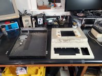
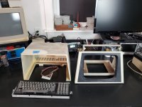
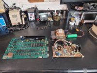
I got it stripped down today. Lots of rust, more than I had expected so a repaint is going to be needed on the monitor frame at least.
Still its always good to get the "Demolition" done so that the rebuild can begin in earnest. The CRT looks pretty good, no photos, it went straight into a padded box in a safe place so I can't cause an "Accident"!

Parts - Bottom and Top Case 1.jpg
Parts - Top Case - Bezel - Keyboard 1.jpg
Parts - Electronics 2.jpg
Transformer 5.jpg

Mike
 
You are very wise. And the PET is exciting !

As you have figured out one of the worst things to do in a fault finding and servicing exercise is to blindly change parts without any solid evidence that they are defective. It often leads to a nasty downhill spiral and failure to repair.

One of the worst cases I have seen of this was an attempted repair on a TTL based video game that had 66 IC's. The person doing it had changed over 30 of the IC's based on hunches & guesswork. The pcb was badly damaged, with more than10 defects of broken and shorted tracks and poor soldering. I was able to fix it for him, but it took much longer than usual, and the pcb will never be the same. In the end the defective IC (found because of an understanding of the circuit's operating theory) turned out to be one he hadn't changed out.
On top of everything you also don't learn much so your skills don't improve.

My company was an office equipment company and it always cracked me up when someone would ask for a discount because they "already took it apart". I'd explain that the hourly rate would be the same but that the time required would likely be longer, not shorter.

Mike
 
There are a number of ways to deal with the rust. One method involved fine glass bead blasting to remove the paint and surface scale, then electrochemical removal of the remainder of the rust and electroplating with Zinc, before the repaint.

For those parts where it is awkward and impractical to do the above, the next best method is to rub down the rust with 300, then 400 then 600 grade paper to remove as much as possible. Rust crystals remain in the pits in the metal and will return under new paint and progress. Unless they are deactivated. The product Fertan (applied with a small brush) is very good to treat the rust (whether the surface is painted or not). It also is very good for rusty transformer laminations. It converts the rust into an inactive blue-black colored organic compound. I used Fertan to help restore a rusty PET VDU:


Fertan is particularly good at seeking out and deactivating rust, it can demonstrate the rust is present in places, even when it is not easily visible to the naked eye.
Thanks. I will look into the rust converter. I usually use evapo rust but that requires submersion. I was not liking the idea that i would need to order 5 gallons or more and my buddy with a bead blaster uses it to etch glassware so i can only use it for cleaning things about once a year when he changes his blasting medium

That vdu write up looks awesome. I'll read it through tonight!

Mike
 
I it were my VDU I would replace that badly rusted 2SC681A horizontal output transistor, as there are plenty on ebay:


These look good too:


Also all of the screws with rusted heads can be replaced too.
 
Last edited:
Back
Top