• Please review our updated Terms and Rules here

Starting my first Pet, a 4032 in desperate need of some love

I had a feeling you would warm to the Fertan, after you tried it. I have been using on radio & TV restorations for more than 20 years now, it is very helpful. You can also brush it on rusty transformer laminations too, it seeps in at the edges and helps prevent more rust forming. You can paint over that, with excellent adherence of the paint to it. Sometimes if it turns the entire stack dark blue to black, you can simply dip the transformer in Marine spar varnish (similar electrical properties to transformer varnish) and it creates a very nice overall finish.
 
I had a feeling you would warm to the Fertan, after you tried it. I have been using on radio & TV restorations for more than 20 years now, it is very helpful. You can also brush it on rusty transformer laminations too, it seeps in at the edges and helps prevent more rust forming. You can paint over that, with excellent adherence of the paint to it. Sometimes if it turns the entire stack dark blue to black, you can simply dip the transformer in Marine spar varnish (similar electrical properties to transformer varnish) and it creates a very nice overall finish.
D'oh. In the rush to get this finished i forgot to mention that part of the list footage was the transformer restoration. I sanded the heavy rust then treated with fertan. I then used a lightly dampened sponge with a green scrubber on it to clean it. There were some black spots of zinc oxide left from the fertan but the texture of the laminate layers made removing that impossible... or at least impractical. I then coated the core with marine varnish... 2-3 coats. When it dried the black spots had turned brown and look like rust in the photos. It looks much better in person than in pictures.
 
I've been on vacation for the past couple weeks so, since i couldn't work on my pet, i planned work on my pet 🤪

I have a couple questions that i could not find answers to below but first i want to thank everyone here for the great entertainment as i read through past pet repairs. The wife wanted to know what had me so engrossed so i told her it was mysteries like "the case of the dead pets", "the flat-lined pet" and a 12 part epic series "Despaerados desperation"

My main question is about the filter caps on the IEEE-488 bus. I had ordered the ones linked in an earlier post but they turned out to be 470pf instead of 47pf. I already removed the originals and really want to find some that look correct but have had no luck. My electronics knowledge is getting better but still really rusty after 25-30 years. Normally i would just leave off the filter caps until i found correct replacements to avoid replacing the parts twice but i am not accustomed to having the ferrite beads instead of a resistor. Will leaving the caps of cause issues until i find replacements or should i put 47pf caramic disks in for now?

My second question would be where to find a guide on fixing the badly corroded edge connectors? They are pretty ugly with missing trace for about 1/4 of their width in places.

Finally i have an opinion question. I have no plans to get rid of this machine in the near future but at some point it may go to someone with poor soldering skills so I'm contemplating socketing all the high failure parts for future serviceability with high quality double wipe sockets. If the board was pristine if never do that but considering its dismal shape...

Stuck in the Caribbean sunshine thinking about vintage computer repairs. 😎
 
Last edited:
Stuck in the Caribbean sunshine thinking about vintage computer repairs. 😎
Often when I'm on holiday I think of my workshop and something I would like to be fixing or restoring or designing. One time on a cruise I designed an entire video Freeze Frame machine with quite a lot vintage style digital logic in it, often staying up late into the night, but at least I could sleep in the next day. When I got home I had about 10 or more sheets of A4 filled with schematics. I designed a memory read-write controller that allows it to store 2, 4 or 8 fields of video:


Probably the ferrite beads that make the small inductor and the 47pF caps form a low pass filter to reduce ringing effects on the leading and trailing edges of the pulses, certainly the frequency must be very high for the 47pF to do anything significant. It will most likely work fine without those caps, so you can leave them out, until the new ones arrive, but those parts might help when long IEEE-488 cables are present. You can just use 47pF ceramic disc capacitors, though they won't have the "style" of the original ones.

I the past I have applied thin shim brass to the damaged connectors gluing it down with epoxy resin. There is also stick down pcb copper tape for pcb repairs that works. But another method I saw, and someone was selling these on ebay I think, is to fit a duplicate edge connector strip permanently fixed to the pcb and soldered to the damaged strips. It lengthens the pcb this way, but it works. Somebody might be able to post a link to those.
 
I am back to the Pet finally. After getting back from vacation I decided to do a quick C64 before digging into the pet. Lol quick C64 took a few weeks. I posted about that on another thread.

I have all the sockets and electrolytic caps replaced and the Big filter cap on the transformer was successfully reformed. The Largest cap on the board was just starting to leak but was not affecting the board.

I found that the /RESET signal went high immediately on power up. It turned out that 2 of the 3 caps on the 555 had corroded through leads. The thought of replacing all the passives on this board is not pleasant.

Now I have a good /RESET signal. I am now looking at the clock on CPU pin 37. Is this much ringing normal? I'd say no but this is my first work on a machine this old.

CPU Clock Ringing.jpg
 
>>> Is this much ringing normal?

Hey, that looks good!

Dave
Awesome, thanks for the quick reply. I guess its time to assemble the Romulator.

I am working on the bare board on the bench until I finish the repaint on the case (Rust). I am guessing that once I check the basics and make sure the video driver bits are OK that I am going to need a screen :-/

edit: oh and I peeked at the CPU with the scope and there seems to be bus contention on as many lines as not

Mike
 
Who's Romulator is it and does it have a copy of my PETTESTER or not? Does it also incorporate a NOP generator? You'll find these useful tools!

Dave
 
Briefly aside, the dead chip count in ScottishColin's PET (Post #2) was the worst I have ever seen, not just in a PET but in anything ever. We were misled at the start by a frequency meter which wouldn't show frequencies below 2MHz and that led us to replace one chip unnecessarily, but for the rest we (or rather Colin, who had by then acquired a scope) followed the broken signals through chip after chip, replacing dud ones as he went. I'm always highly resistant to the idea of replacing chips without due cause.

Let's hope this one doesn't turn out to be like that one!
 
I have wielded my trusty Wellers flaming iron +5 and completed the assembly quest.

Sadly i must now complete an epic side quest called honey do's for you know who so i probably can't test it until tomorrow...
 
OK so I am at a bit of a decision point. The Romulator is ready to go but the frame that holds the CRT itself is taking a 24 hour Fertan treatment, after we got some unexpectedly warmer weather. I sanded all the rust down last night and since it's supposed to be 66F tomorrow I can prime and paint it then.

I also cleaned up the VDU board and replaced the rusty SCR so I will be ready once everything can go back together.

In the meantime I was thinking of just running the NOP generator and working on the address lines. I have good /RESET and Clock so what would you guys do next?

Can you tell I am a process guy that likes to work a logical path and so I get hung up when working on something I have not touched before?
 
It's good that you are a process guy... Same as me!

With the NOP generator running, the first thing to check are the buffered address lines. BA0 should have a frequency of 250 kHz, and each successive buffered address line half the frequency of the previous buffered address line.

Let me know when you have done that.

You can then test the 4:16 decoder, the ROM chip select lines, the DRAM refresh lines and the DRAM /RAS and /CAS lines.

You can also look at the 'read' half of the buffers from the video RAM and look for data bus contention.

All signals should give you nice TTL voltage levels...

All that from a NOP instruction!

Dave
 
OK wow, this is encouraging.

The BA0-BA15 lines are each half the frequency of the preceding one at TTL levels. I measured them on the 74LS244s.

The Decoder has good TTL signals on the outputs but I don't have a logic analyzer, nor have I used one in a few decades, so I can't say they are valid based on the inputs.

The ROM chip selects all look OK to me except UD7 that looks like it is selected twice (Or has a brief 5v peak in the middle of the select). This is an unpopulated socket because the chip was rusty and a pin fell off
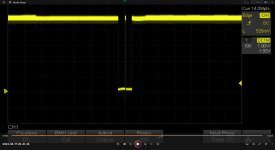
UD7 ROM Chip Select.jpg

UD11 and 12 are also unpopulated, as they were when I got the machine.

I am a bit confused on the RAM, aren't /RAS and /CAS the refresh lines? They do have good TTL levels.
The Din and Dout lines are tied together on the schematic !?! They have bus contention but I am guessing we are not there yet.

For the video RAM buffers, which is the read side? relative to the RAM so the ESD0-7? They look fine, the other side is not so hot.

It is a bit late so I plan to recheck these, and record the scope readings in the morning

I got the first coat of primer on the CRT chassis today so I am hoping to be ready to put a tube in this beast by Sunday. Tomorrow is supposed to be in the 60s for more primer and paint.

Mike
 
You probably went a bit further than I wanted you to, but it has raised a few questions I can answer.

The first question I have though is "what is the part number on the PCB". I want to make sure we get the correct schematics to work from before we start!

The little 'glitch' you are seeing on the chip select of UD7 is expected. Nothing is perfect in digital logic, especially when the logic is switching. Sometimes you see these and sometimes you don't...

The /RAS and /CAS signals on the DRAM are not just for refresh. During a refresh cycle, a refresh counter is output on the DRAM address lines and the /RAS line activated - but no /CAS.

For a normal read or write cycle, you get both a /RAS and a /CAS signal. Half of the address lines from the CPU are sent to the DRAM on the /RAS signal, with the other half of the address lines are sent to the DRAM on the /CAS signal.

The /CAS signal should only be activated for the bank of DRAM that is being accessed.

All of the signals for the DRAM are largely common (with the obvious exception of the data lines). The main exception being the /CAS line.

The DIN and DOUT lines of the DRAM being commoned is OK! The DOUT pin is tristate when this is not a read cycle!

Dave
 
Dave,

It is an 8032089 Universal dynamic Pet board. I am working off the 8032090 schematic. I do use the schematic from the 8032 manual since I have an original at the bench that is easier for me to read then the scanned ones. I have the 4032 manual as a .pdf. My understanding is its the same board with some jumper changes?

The UD7 quirk is interesting since its not just ringing but a full swing to +5v and back in the middle of the pulse.

The RAM sounds interesting. I think that all we used in college was static and my C64 and Amiga diagnostics focused on the bus' (It almost always seems to be the address bus on those machines). I admit that I downloaded the data sheet for the RAM then only looked at the pinout page. I will have to check out the rest.

Mike
 
Excellent. It always pays to double-check the PCB code. Commodore used to ship some 'frankenstein' machines at one time (get stuff out of the door to satisfy demand) so you may end up with some strange combinations.

Also, the machine could have been 'repaired' (aka bits swapped) or 'upgraded' with similar results...

As the address bus changes from one value to another, it doesn't do it in a 'nice' way. The 74154 address decoder just decodes the upper four (4) address lines so, technically, anything could (and will) happen when the address bus changes state. However, data is only actually read and written on a specific edge of the clock, so the address bus is actually ignored during this transition period.

Ok, I will get some more signals for you to have a look at when I have made some little bits fir my camera controller and done my chores for the day (washing up in this case).

Dave
 
Ok,

So you have a univ2 yes?

Look at schematic sheet 5.

RA1 through RA7 are the DRAM refresh counter signals. They should be oscillating away to themselves with RA1 at 500 kHz and each higher refresh line at half of that frequency.

If you look at buffers UE8, UE9 and UE10 - these multiplex either the refresh counter signals or the CPU address in two 'chunks' (corresponding to the /RAS and /CAS signals) onto the DRAM address pins.

The corresponding buffer should present the inputs to the outputs when pins 1 and 19 are LOW.

Does this make sense?

Dave
 
Back
Top