To stop the possibility of someone else making the same oversight, I have modified the head moving code to use A:
I'll respond to this first since it's where I made the most "groundbreaking" discovery.
I ran the head moving program (this time making sure to read the instructions and change the the lines in the code to use A: instead of B: ) and I got the head to move.
Immediately I noticed a very glaring issue. I had the head move to the same location then go back several times.
More than half the time, the head would be quite far off where it needed to be. I marked spots on the rail just to make sure I wasn't seeing things.
The rails themselves are very well lubricated, so the only reason I could think of this happening is that the stepper motor is more stuck than I realized (the motor seems fine to me as the head seems to move with light force, but then again, I've never owned a working TM-100 before so I wouldn't know. I've already attempted to lubricate it from the outside. But my best bet would be that my lubricant isn't able to fully penetrate the motor bearings.
Would that be a safe guess to make? If it were just an alignment issue, it would still be moving to the same spot consistently, correct?
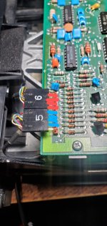
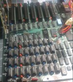
The last thing I noticed. I noticed some of the wires on connector 5 on the floppy drive had been pushed out. I pushed them back into the connector and tested the continuity to make sure they were ok. It seemed fine, until I realized that everything except for the black and exposed wires were making continuity? I'm not sure if there's a short somewhere on the head itself or if it's just supposed to be like this. But I found it really weird. I checked to see if it was an issue with the main board itself, but none of the pins that connect to connectors 5 and 6 have this short. I've attached a photo of which pins are shorting out. The pins colored red are shorted on connectors 6 and the blue colored pins are shorted on connector 5.
So what is 'address mark not found' ?
At [
here] is a data sheet of a controller chip used in PC family floppy controllers.
Figure 3 (on the last page) shows me the low-level format.
On page 5-12, you will see "MA (Missing Address Mark)" and a description of the conditions under which the controller chip flags that error.
So in other words, the floppy controller just isn't finding what it's looking for in the place where the head moves to?
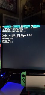
I was able to replicate what you saw (the XUB displaying 'Error 2h!') by disconnecting the two heads on my TM100-2A, and having a known bootable floppy inserted.
A drive with bad head alignment would be another possible cause.
Hmm, I wonder if it could be relating to that short on connectors 5 and 6 I noticed? Aren't connectors 5 and 6 the ones which connect the heads to the main board? But I guess that wouldn't make much sense considering that it sometimes reads.
Dirty heads is another possibility.
I'm fairly certain the heads are clean, I've gone over them with isopropyl alcohol multiple times now. From what I can see there doesn't seem to be any other visible forms of corrosion or debris that would be causing the heads not to read.
And because we know that your machine sometimes reads the boot sector of a boot floppy okay, I don't expect the XUB to display 'Error 2h!' at every floppy boot attempt.
I did another experiment last night to test this theory after running the stepper motor movement program. I did this with the XT-CF removed, I figured for the most part, any error codes the XT-CF BIOS would throw up would be mostly irrelevant since it seems like it's just an issue with the stepper motor not going where it needs to.
Anyway, I inserted my DOS 3.30 disk, and attempted to have the floppy drive read the disk 10 times. 2 out of the 10 times, the computer gave me a "disk boot failiure" error. the other 8 times it would just go straight to cassette BASIC.
Based on what you said, it seems like those 2 specific instances where I got an error would be times where the head actually moved to the boot sector, then failed to move where it needed to read on the disk next.
If it were me, I would fix that before doing anything else. Even if bad RAM is disabled, there is a chance it can still interfere with other things. Are you sure you had the RAM DIP switches set right when you experienced the parity error? Sometimes having them set wrong can cause DOS to use memory that isn't there and go boom. I'm guessing it passed the initial RAM test?
I did some experiments to check on the RAM last night. It seems like whatever is causing the parity error is in BANK 2. I enabled BANK 2 on the DIP switches and it produced the parity error 1 once again. The first time the parity error happened, all 4 banks were enabled.
It does pass the initial RAM test with 128K regardless of whether I enable banks 2 and 3.
That can be tricky to track down. Ideally you would want to use a RAM tester like Checkit,
If it were me, I would REALLY want to get the machine booting with either another 360k drive or a 720k-1.44mb drive and test the motherboard first.
I definitely plan to try the known working 360k drive I have in my AT on my XT, assuming fixing the movement of the head doesn't resolve the read issue. I just.. really don't want to take the AT out.. (it's been in the box most of its life and it's an AT so it weighs a ton. That and I just don't have space to bring it out most of the time). If or when I do try the AT's 360k drive, I will give Checkit a try for sure.
In regards to the stepper motor on the floppy drive, I've seen a couple videos of people completely disassembling the stepper motor and lubricating the bearings individually. Is this advisable?
 it's got 128kb fitted. That's definitely a good push in the right direction though, thank you for that!
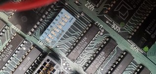
")