• Please review our updated Terms and Rules here

Tandon TM100-2 appears to be in mechanically working order, but never attempts to read disks.

This is it. I can buy medical equipment on eBay, but that doesn't mean that I can then successfully diagnose people's medical problems. I need to know how to use the medical equipment, and in using that equipment, know what to expect in the way of readings/measurements. Etc.
I'll be honest, the majority of electrical knowledge I have is mostly just stuff I've learned from family, the internet, and reading.
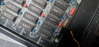
I've had very little formal training (finishing general education to work on obtaining a degree in electrical engineering). I also didn't think much about how each of the wires is connected to the head, every wire would be making continuity.
I hope I don't come off like I think I'm an expert on this stuff, I know I'm not and I greatly appreciate you and everyone on this forum's assistance so far.

I have a 200 foot long cable, a cable that has 100 wires in it. I need to verify that there are no breaks in any of the 100 wires. If I was to use the resistance setting on my multimeter, I would need to glance at my multimeter every time that I move the probes to a different wire. My job would be much easier if I didn't need to look at the multimeter. That's where continuity mode helps me. After I move the probes to a different wire, the beep informs me of 'continuity' in the wire.
I think I understand now. So the continuity setting is best for making sure an electrical signal is getting from point A to B on a wire or trace rather than trying to check continuity on a coil where multiple wires may be connected together but they may not necessarily have the same resistance value.
 
I think I understand now. So the continuity setting is best for making sure an electrical signal is getting from point A to B on a wire or trace rather than trying to check continuity on a coil where multiple wires may be connected together but they may not necessarily have the same resistance value.
As far as I am aware, there is no international definition of 'continuity'. For example, for all I know, in the AC power generation/delivery industry, if a technician unexpectedly measures 3,423 ohms between the primary and secondary windings of a HV transformer, he/she may declare that continuity exists.

As far as I am concerned, there is no 'It is best to use continuity setting in situation XYZ.'

By default, use the resistance setting, and again, one needs to know roughly what reading/value is expected. Think of the continuity setting as an optional extra that can be helpful in some situations (such as the example I gave where it was helpful not to keep looking at the meter, and the expected ohms per measurement was below 100).

For example, if I am seeing if the frame of a floppy drive is adequately connected to the computer case, I would be worried if that measured say, 20 ohms. My multimeter, in continuity setting, is going to beep in that situation.
What if that was a damaged trace that was measuring 20 ohms !
Gotcha, that makes sense, I think I get it now. Thank you for the explanation :)

In other news..

I pulled and reseated the RAM in bank 2 multiple times, then tried swapping the RAM from bank 3 to bank 2 and vice versa, neither solution caused the memory in bank 2 to be counted during the initial check. I made sure the DIP switches were set correctly to use banks 0, 1, and 2, but it still showed only 128K on the initial RAM check. (I still need to check and see if the parity error occurs with bank 3 enabled).

I did however manage to get my SixPack Plus working with the computer, which brought me up to 512K (384K on the SixPack, 128K on the motherboard). This allowed me to run CheckIt. I enabled banks 0, 1 , and 2 (after swapping the memory from bank 3 to bank 2), which did not cause a parity error this time. However, when running the memory check, it did not seem to look over bank 2 at all. Only banks 0 and 1 as well as the banks on the SixPack were checked, which seemed to all be working fine.

I haven't had the chance to check the track 0 sensor yet, or to try moving from track 20 to track 30 repeatedly. I hope to be able to do that today. However, while I was running Checkit, I ran the floppy drive test. I've attached a photo of my results.
As you can see, the poor little Tandon really struggled. I watched the head attempt to move, however, sometimes it would be able to move freely (to the wrong location), other times it would begin shaking, as if it were seized up.

I also did a quick test of Elite Plus for fun. Other than the plethora of issues going on with the computer, everything else is running smoothly! It looks so cool in VGA!
 

Attachments

  • 20221103_221900.jpg
    20221103_221900.jpg
    1,017.4 KB · Views: 8
  • 20221103_220746.jpg
    20221103_220746.jpg
    1,011.6 KB · Views: 8
I pulled and reseated the RAM in bank 2 multiple times, then tried swapping the RAM from bank 3 to bank 2 and vice versa, neither solution caused the memory in bank 2 to be counted during the initial check. I made sure the DIP switches were set correctly to use banks 0, 1, and 2, but it still showed only 128K on the initial RAM check. (I still need to check and see if the parity error occurs with bank 3 enabled).
Assuming bad RAM chips, one has to keep in mind that there could be bad RAM chips in both banks.

However, when running the memory check, it did not seem to look over bank 2 at all. Only banks 0 and 1 as well as the banks on the SixPack were checked, which seemed to all be working fine.
CheckIt cannot tell what memory is where (motherboard or card). It just sees a block of RAM, and it will be interrogating the BIOS for the RAM size.

The RAM size figure in the BIOS is determined by the POST, which in the IBM 5160, uses a simple look-and-see approach, which per the 'flawed methodology ...' section of [here], doesn't cater fully for bad RAM chips.

What you could try is:
1. Remove the SixPakPlus; then
2. Set the motherboard RAM switches to enable all four banks; then
3. Use the 'OPTION 4: DEBUG' section of [here], using "2000" instead of "8000" [your motherboard bank 2 is at 128K --> 128K = 20000 hex --> 2000:0]

{ Note that I am about to 'lay low', heading on a holiday for a month. }
 
Most DMMs with audible continuity testing are (a) low volume and (b) slow. This can be frustrating if you're checking a lot of circuits. I was thinking about a DIY with a comparator and a very loud audio source. Does anyone have a preferred DIY version? I suspect that the whole thing could be done with a cheap MCU.
 
Gotcha, that makes sense, I think I get it now. Thank you for the explanation :)

In other news..

I pulled and reseated the RAM in bank 2 multiple times, then tried swapping the RAM from bank 3 to bank 2 and vice versa, neither solution caused the memory in bank 2 to be counted during the initial check. I made sure the DIP switches were set correctly to use banks 0, 1, and 2, but it still showed only 128K on the initial RAM check. (I still need to check and see if the parity error occurs with bank 3 enabled).

I did however manage to get my SixPack Plus working with the computer, which brought me up to 512K (384K on the SixPack, 128K on the motherboard). This allowed me to run CheckIt. I enabled banks 0, 1 , and 2 (after swapping the memory from bank 3 to bank 2), which did not cause a parity error this time. However, when running the memory check, it did not seem to look over bank 2 at all. Only banks 0 and 1 as well as the banks on the SixPack were checked, which seemed to all be working fine.

I haven't had the chance to check the track 0 sensor yet, or to try moving from track 20 to track 30 repeatedly. I hope to be able to do that today. However, while I was running Checkit, I ran the floppy drive test. I've attached a photo of my results.
As you can see, the poor little Tandon really struggled. I watched the head attempt to move, however, sometimes it would be able to move freely (to the wrong location), other times it would begin shaking, as if it were seized up.

I also did a quick test of Elite Plus for fun. Other than the plethora of issues going on with the computer, everything else is running smoothly! It looks so cool in VGA!

If you want to make your life a little easier, you can get standalone 41xx memory chip testers with ZIF sockets on EBay for quite reasonable costs.

The one I got helped me test both 4116 and 4164 chips when I was starting to fix my 5150. Found 3 bad chips in the PC, but also validated the chips I was using as replacements were good too.
 
Assuming bad RAM chips, one has to keep in mind that there could be bad RAM chips in both banks.


CheckIt cannot tell what memory is where (motherboard or card). It just sees a block of RAM, and it will be interrogating the BIOS for the RAM size.

The RAM size figure in the BIOS is determined by the POST, which in the IBM 5160, uses a simple look-and-see approach, which per the 'flawed methodology ...' section of [here], doesn't cater fully for bad RAM chips.

What you could try is:
1. Remove the SixPakPlus; then
2. Set the motherboard RAM switches to enable all four banks; then
3. Use the 'OPTION 4: DEBUG' section of [here], using "2000" instead of "8000" [your motherboard bank 2 is at 128K --> 128K = 20000 hex --> 2000:0]

{ Note that I am about to 'lay low', heading on a holiday for a month. }
That helped a bunch! I was able to diagnose that 7 chips (out of both banks 2 and 3) were bad. I was able to find enough that were good to fully populate bank 2. Bank 3 however is now almost completely full of bad ram..

Have a good break! Hopefully things will be sorted out by the time you're back.
 
If you want to make your life a little easier, you can get standalone 41xx memory chip testers with ZIF sockets on EBay for quite reasonable costs.

The one I got helped me test both 4116 and 4164 chips when I was starting to fix my 5150. Found 3 bad chips in the PC, but also validated the chips I was using as replacements were good too.
Welp, I guess that's what I'll have to end up doing. I don't suppose there's a way to bring bad chips back to life? 😅
7 4164 chips in bank 3 are not functional.
 

Attachments

  • 20221104_195930.jpg
    20221104_195930.jpg
    1.4 MB · Views: 4
Nope--they're dead, Jim. Some might work in lower-speed installations, but there's no guarantee.
Figured as much, oh well.

I did some experimenting this weekend and checked the track 0 sensor on the drive. I tested for continuity on it when the switch was pressed, and it seemed fine to me. I don't know if it's that my drive is a later revision or not, but the colored part that actually actuates on the track 0 sensor is green and all of the wires on the switch are soldered in place. In most references I've seen, the actuating part of the switch is red. I doubt it's significant but I just found it interesting.
Anyways, after checking that and putting it back, I decided to try and run the checkit floppy test without the logic board covering the head. I recorded a video of it here.
One thing I realized after watching some demonstrations of working TM-100 drives was that my drive doesn't make that usual buzzing noise when the heads are attempting to access a floppy disk.

Before I had taken out and inspected the track 0 sensor, I had also once again manually controlled the stepper motor using cassette BASIC, in order to try and record a video of the inconsistent stepping. Here.
I had the drive repeatedly try to move to track 20, and each time it would produce a different result. Sometimes it would move a consistent distance (I wouldn't quite say it moved halfway down the rail), and others it would sort of jitter, as if it was hitting the back of the track and not stopping after hitting the track 0 sensor?
I'll look more into it when I get home.
 

Attachments

  • 20221106_235545.jpg
    20221106_235545.jpg
    648.1 KB · Views: 0
  • 20221106_235525.jpg
    20221106_235525.jpg
    952.2 KB · Views: 0
The "buzzing" usually means that there's a mismatch between the seek stepping time and the time best used by the drive. If the programmed seek time is too slow, the drive will buzz while seeking.
 
Back
Top