• Please review our updated Terms and Rules here

troubles with the CBM 3022 printer

giobbi

Veteran Member
Joined
Dec 23, 2012
Messages
1,002
Location
São Paulo country, Brazil
Hi all,

I own this printer that was tested last time in 2021 and labelled as "working ok" by me.

Now I was trying to make some prints but I'm having some issues.

I switched it on and I pressed the FEED button a few times while I was trying to understand how to load the paper: it seemed to work fine, moving the printer head and the tractor as expected.

When I finally loaded the paper, I tried to switch it off and then keeping the FEED button pressed while power on (it should be the self test). Nope, just the red LED and nothing more, no activities, nothing. Since then, when I press the FEED button, only the red LED lights on and nothing happens.

I haven't the printer manual and I didn't find an English version (just German version, that to me is like ancient Greek). So I don't know what the red LED means and what's happening.

I also tried an open4,4 : print#4,"hello" from my 8032 connected to the printer, but I got a "device not present" error.

Any idea?
 
...The interesting part is that today, after a night sleeping, it worked again for a while. I switched it on and it did the normal reset. So I tried to run the self-test, and it did it correctly... for a while. Then it stopped to print (no head noise), no tractor feed, just the head moving left and right. Switched it off, waited for a while, it began again doing the self test. But after few tests, it stopped again to respond, just showing the red LED when I press the FEED button.
The printer is a little bit rusty, so actually I need to clean it, maybe opening and removing some parts... but I'm puzzled with this strange behavior.
 
It is most likely a bad connection somewhere that works and then doesn't...

Remove the connectors and reinsert them a couple of times to 'wipe' the contacts.

If you have any 'proper' contact cleaner, use a little bit of that to help clean and lubricate the contacts.

This should work a treat...

I assume there are some DIP switches somewhere (e.g. to set the IEEE488 address and other features). These can also make bad contact. In this case, either make a note of the setting (or take a photograph) before you start and ensure you set the switches back the same after exercising/cleaning them.

Dave
 
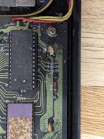
I have a 3022; mine doesn't have any DIP switches to set the address, just three jumpers that are by default set to 4 but can be broken to change the address (see photo).

The 3022 German manual is here:


Just the text can be downloaded and translated with Google Translate if that helps.


Attachments

  • PXL_20240717_194012220.jpg
    PXL_20240717_194012220.jpg
    2.1 MB · Views: 9
well, I opened it removing the mechanical assy (it's like to tearing apart a tank LOL), and I cleaned all the connectors.
Then I removed the 4 socketed chip (the big ones are labelled C010750-03 but according with the PCB label should be 6532, then there's the 6504 CPU [I absolutely need to buy a spare 6504 before they become unavailable] and the 901472-03 ROM chip) and I cleaned and lightly sanded all the pins. I sprayed some contact cleaner into the sockets and put the ICs back in place.

I also removed and carefully cleaned the print head flat cable (the contacts are unpeeling from the plastic layer so I think it's wise not to remove the cable again).

Finally, I put everything (temporarily) back in place, and... nothing. No results, just the red LED that lights on when I press the feed button.

It seems to me maybe there's some issue involving the board; I need to investigate, trying to see if there's some signal at the ICs pins. Unfortunately I'm not an electronical engineer so my skill and knowledge is limited. Those chips are old, and MOS chips never were the more reliable chips in the world, especially after almost 50 years...

BTW looking at the size of the ROM image file, I can tell the ROM is a 32 kb. But can I replace it with a 2732 plus the same adapter I would use in a PET, or is there any reversed signal, like for the 64 kb ROM in the 8050/8250 FDD?
 
When I had problems with my 3022, I was told it was a European variant of the 2022 so 2022 schematics/manuals were applicable. Probably worth checking your motherboard against P19 of the manual linked to below:


Also, the printer mechanism is an Epson 3110; technical reference manual is here:


Colin.
 
OK it *seems* I've found the culprit: with the ROM inserted, all the address signals are stuck to high. Removing the ROM, they come back.

So I tried to use the same adapter I use in the PET for the 2732 EPROMs in place of the ROMs... and of course it doesn't work ("nothing is easy", feat. Jethro Tull LOL). The printer falls into an endless head movement left to right to left, and nothing more.
I suspect I must to invert CS signal like it's done with the 2764 EPROM into the 8050/8250 etc. FDD. Does anybody have any clue about that?
 
Yep, looks like they use the active HIGH chip enable (CE2) of the 2332 just to throw you!

Just invert it (with one gate of a 74LS04) and drive the active low /CE and /OE (as appropriate) of the EPROM you are using.

Dave
 
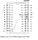
Resume of the day.... I took the example of the 2764 -> 2364 adapter I did for the 8250 FDD and I adapted the idea for this adapter.
Then I take the Ray Carlsen's schematics for the 2732->2332 adapter (in the past I made some PCBs based on it) as starting point.

2732SUB.gif
I cut the CE <--> CS1 signal (from EPROM pin #18 to Socket pin #21 and I used an smd 74LS04 glued on the PCB.
I connected the pin #9 to the socket pin #21 and the pin #8 to the EPROM pin #18 (plus of course Vcc and Vss).
So the schematics is SOCKET #21 -----|>° ---- EPROM #18 ..... And of course it doesn't work LOL

However... I've tested the address lines and now even without ROM they're stuck high. I've noticed the RESET line is high (in my first test it didn't happen, so I was inducted to believe the problem was the ROM). I always forget how read the schematics, so I never remember if RES with the ___ notation above should be considered as HIGH or LOW... I tested the 555 pin #3 and it seems to me it stays low since the beginning, so maybe it's just an issue on the reset line ...?

EDIT: Forgot to mention that for the RESET line test I removed all the socketed ICs, just to be sure they're not the culprits. I also did a silly test: just to see if the CPU was bad (address lines stuck high), I replaced the 6504 with an Atari 6507 CPU. Looking at the datasheets, it seems to me the only difference is the pin #3 (IRQ on 6504, RDY on 6507). I suppose it should not interfere to the address lines (they should pulse anyway).... or not? Because even with the 6507 they're stuck high. Of course it means nothing if the reset line is bad.
 
Last edited:
RES with a bar above it is active LOW (i.e. after the power has been applied, the /RES should stay LOW for a while and then go HIGH).

Don't get confused though. Unlike a PET, the 555 timer is NOT the reset circuit!

It appears to generate the pulse that fires the transistors that operates the print head solenoids...

Dave
 
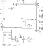
Dave, based on the schematics from Zimmers (https://www.zimmers.net/anonftp/pub/cbm/schematics/printers/cbm3022_pcb2.gif), it seems to me the 555 is the reset circuit...? :unsure:
EDIT: - Strange, there are two pages, one mentioning a 555 as you told, the other mentioning the 555 as reset circuit. But on the PCB there's just one 555. I'm a little bit confused LOL
However the reset pin is high, so it should be ok...

1721327937996.png
 
OK, so we are using different schematics...

I wonder which one is applicable to your actual printer...

Dave
 
OK, so we are using different schematics...

I wonder which one is applicable to your actual printer...

Dave
none of them. I just discovered my board is different, the 555 pin #3 goes to the pin #13 of a 74LS09 (there aren't any 74LS09 in the two different schematics). I need to remove the board to understand better, however if we're expecting an HIGH at the reset line, this is not the issue. I'm wondering who's keeping the address line stuck to high... can you tell me what could keep the processor in this condition?
 
Last edited:
The CPU has to be reset in order to start operating correctly.

No reset signal probably means that the CPU doesn't start up properly.

If the CPU reads (and executes) an invalid unstruction from the ROM then that can cause the CPU to just give up...

Dave
 
The CPU has to be reset in order to start operating correctly.

No reset signal probably means that the CPU doesn't start up properly.

Well, the reset is high, so we can assume the reset line is ok, am I right? (I'm doubting of everything LOL)

If the CPU reads (and executes) an invalid unstruction from the ROM then that can cause the CPU to just give up...

One of the first tests I did (I talked about in a previous message) was to check the CPU address lines, and I discovered they were stuck high. So I remove the ROM and test the address lines on the CPU again, just to discover that now they were pulsing. I did this test a couple of time in a row and that leaded me to believe the problem was the ROM.
So I built the adapter with an inverter: SOCKET #21 (CS1)-----|>° ---- EPROM #18 (CE) (as described in my post #13) and I tested it, with no luck.

So my questions are:
- did I build the adapter in the right way
- can we assume the address lines should pulse even without the ROM in place?
 
You can only determine that the reset line is OK if it has been observed to be LOW shortly after the power supplies have stabilised and then transitions to HIGH.

If the reset line starts out HIGH when the power supply rails have stabilised, then the reset signal has not done its job.

Your adapter looks OK...

If the ROM isn't in place, all bets are off I am afraid. Toss a coin to see what will happen...

Dave
 
Back
Top