• Please review our updated Terms and Rules here

VGA graphics for the TRS-80 and others.

Why not start a project using forum? It is as useful as all these social media sites for developers.

Countless projects on these social media sites that say they are building this or that but if you follow thru on project, it was never finished.

This project sure shows us what can be done with hard work.

This is excellent work. As far as speed, I would think a 50 mhz eZ80 with block move insturctions etc could make a dent in speed problem.
 
I would think a 50 mhz eZ80 with block move instructions etc could make a dent in speed problem.


That EZ80 looks like a nice part, but operation to 50 MHz doesn’t really lend itself to vintage-like expandable hardware layouts – more so to small, so-called “SBC” designs. IMO, if you want a Z80 system running that fast you’d be better off just implementing a Z80 core and all your peripheral devices (HDD emulation, video generation, etc) inside a suitably large FPGA.

I’m still procrastinating about where to go next in my TRS-80 adventures. One thing I don’t like about my TRS-80 Model 1 clone are its limitations when it comes to expandability. Daisy chaining external devices on the Expansion Port is not only a packaging headache, but is only electrically viable to a limited extent.

A TRS-80 Model III clone built around S-100 bus-compatible boards would be awesome as far as potential for expandability goes. I’d like my clone to have a programmable clock generator, with a “turbo” button like those IBM-compatibles used to have. You’d run in stock clock mode for software compatibility and standard IO operations, but have the “turbo” clock option for when you want to do some number crunching. The clock generator could be built to detect IO operations and automatically drop out of turbo mode.

The Z84C is available in a 20 MHz speed grade, but to get that to work reliably over a (mostly) IEEE-696 compliant S-100 bus, I’d have to limit the back-plane to something like only four or five slots.

S-100 cards are big and you can pack a lot of SMD circuitry on to one, but such a limited number of slots wouldn’t exactly make my next potential clone build super expandable. 20 slots would be more like it, but I’d have to temper my speed fantasies to something more like 6 MHz – hence the procrastination. Though 6 MHz is still 3x faster than a stock Model III, so not all that terrible as an upper limit.

To go with such a build, I’m also considering doing S-100 versions of at least the B and C variants of my VGA video cards.

Decisions, decisions.....
 
Last edited:
A left field suggestion I’d toss out is instead of using S-100 go with a pin arrangement close to ISA and build it on a passive backplane that fits in a generic PC/AT/ATX case. (Or make the base computer itself an ATX form factor.) “True” S-100 is sort of a hassle with its huge card size and need for voltage regulation on every card. 8 bit XT slots have 20 address lines, enough for the addressable space of Z180 derivatives, and maybe it might even be possible with a little help to adapt the Z80 bus cycle so at least some PC peripheral cards could be used unmodified with appropriate software? (The bus in the 5150 borrowed heavily from the 8085-powered Datamaster system...) Obviously you’d need some kind of MMU to use memory mapped peripherals, but port IO should be vaguely possible even with a Z80?

Totally just pulling this out of my rear here, I haven’t sat down to puzzle out what dealbreakers there might be.
 
I have been reading up on the ISA standard and considering other options, but am strongly gravitating towards the S-100 standard now for two main reasons:

1) I don’t currently own an S-100 system and would like one.
2) Any individual card that I design for such a system won’t be entirely bespoke and will have a broader application / appeal.

IEEE-696 certainly is a bit of an ugly Frankenstein of a standard and will never support a distributed system with a really impressive master clock rate, but I guess these are the kind of qualities that give vintage computing most of its appeal!
 
Way I see it there is 3 groups.;
1. legacy folks that want to restore TRS80 exactly like they were when made.
2. This group wants to pickup where Tandy left off and take OS and hardware to next level.
3. This group cannot understand group 1 or 2 at all.

I have went thru a design process for hardware compatiable with model 4. Using a Z80 it would be nearly 100% compatiable. You can increase clock speed some but if you increase too much then OS needs modifications. And it just keeps getting deeper and deeper. Timing routines, debounce many many things were designed to operate at a specific speed with some room to work.

I am not sure why anyone would want to build a new computer and use a Z80, we have plenty of hardware already available plus emulators.

I am interested in moving forward from where it stopped.

Like with many microchips it is hard to be everything to everyone. That is why I have worked on advancing OS for operation not 0nly under Z80 but also eZ80 and Z180.

Plus Zilog have several newer versions available mainly used in controller arena.

IMO.....It is best to work on a OS and hardware that supports the entire Z80 family (and decendants).

Why I spend my time working on this I am not sure, perhaps mental illness (or thats what my wife thought after she asked if all these hours could make money).

But I keep doing it.

I encourage each of you to see your projects through. 99% of projects I read about on websites are never finished and just fade away.
 
I'm slowly getting back to this expandable Model III clone on and off in my spare time. I have abandoned the idea of using the S100 standard for this project and have come up with my own eurocard-based format.

I'm currently toying with the idea of enhancing the video generator with the option of basic color, utilising unused space in the Model IIIs memory map for the colour RAM. To each character location I'd like to assign one bit for each primary colour and one reverse bit, permitting any character position to be displayed in one of 8 colours, either normal or "reversed" (aka the PET).

This RAM will need to be initialized on start-up. I haven't had a chance to delve into it yet, but is anyone out there familiar enough with the Model III OS to know if there is any dead-space in the boot sequence code which could be appropriated for this task? Probably a long shot here, I'm thinking perhaps some code related to some obscure function which won't necessarily be missed. In any case there are enough bytes in the boot screen message to do what I need, so if there is no other option I could heavily contract or completely delete the boot screen text.
 
The middle letter I in the startup message ("Radio Shack Model III Basic") is the documented way to determine Model 1 vs. Model 3 ROM -- if peek(293) = 73 then model 3 else model 1. For compatibility you may want to leave that byte unchanged.

Alternatively, other ROM patches have overwritten the code that writes low-speed cassette bytes as that capability is the least used.
 
Hmm, that's sneaky with the model detection. Not sure I'd like to overwrite the low-speed cassette code as I've got lots of slow baud rate software recorded with/for my Model 1 clone and would like to retain compatibility between machines. I guess the low-speed cassette code isn't cycled through on the boot sequence so at the very least I'd have to find a few bytes of space there for a jump if I were to go that way?

I think I have a better idea. I could use the power-on timer to set an IO port-controlled register bit which forces the address decoder to select an alternative ROM on start-up. This would be a custom ROM programmed to initialise my colour RAM and perhaps in the future to configure whatever other custom hardware I might expand the system with. An IO port write instruction to reset the ROM control bit would then revert the system to normal Model III operation.

This way I wouldn't have to modify the original OS at all and I'd have a lot of scope/flexibility for future system add-ons.
 
An IO port write instruction to reset the ROM control bit would then revert the system to normal Model III operation.

The ROM switch-over should trigger a monostable to deliver a CPU-only reset.

In the specification I've come up with I have two reset lines. !POR is the power-on-reset and is intended to be used globally, resetting both the CPU and all peripherals requiring such. !CPUR is intended to be used to reset the CPU only. These lines are open-drain/collector driven and resistively pulled high. !CPUR is used as an input signal only on the CPU card, where it is ANDed (functionally ORed) with !POR to drive the Z80 reset pin.
 
I'm currently toying with the idea of enhancing the video generator with the option of basic color, utilising unused space in the Model IIIs memory map for the colour RAM.

Incidentally, this unused space is located in the 1KB block allocated by the stock machines address decoder to the keyboard; 0x3800-0x3BFF. Only lines A0 through A7 are used to scan the memory-mapped keyboard. During a scan these address lines are asserted sequentially and individually, so the keyboard in reality only uses the first 128 bytes of the 1KB block decoded for it.

It is the top 512 bytes of this block that I wish to utilise for my colour RAM. There are 1024 character locations in the video display (64 columns by 16 rows) and I need 4 bits per character.
 
Last edited:
Bank swapping the ROM would certainly be cleaner. As to the ROM patch, sounds like you could live with overwriting the high-speed tape routines.

Regarding the keyboard matrix, there may be some programs which use the $39xx, $3Axx, $3Bxx mirrors but I doubt there are many. Somewhat more common is using $38FF to check if any key at all is pressed so limiting access to the $38xx range might cause problems. But these are much more minor considerations than the Model 1/3 detection.

Though if you're switching out ROM why not make is so writing to the ROM writes to colour RAM? Or, for that matter, the video data RAM itself? With the option to switch out the ROM entirely and have full read/write access. Generally that'd be much faster for Z-80 display operations.
 
Though if you're switching out ROM why not make is so writing to the ROM writes to colour RAM?

That seems like a pretty straightforward solution; maybe there are programs out there that for some obscure reason write to ROM addresses but I would think that should be rarer than programs that are sloppy about keyboard addressing. Obvious downside is you'll need to bankswitch if you want to *read* color RAM, but you can work around that by shadowing that information somewhere else.

If you're mapping 1K of color RAM anyway why restrict yourself to 4 bits with one for reverse video? Might as well implement a PC-style attribute set with 4 independent bits for foreground/background color. (Or if you only want 8 colors make the extra bit "blink", everybody loves that.)
 
Yes, I forgot about the 0x38FF key press check with all A0 through A7 asserted, but that is still well outside of the range 0x3A00-0x3BFF that I am tentatively contemplating using for my colour RAM. If putting the 512 bytes of colour RAM there my hardware would obviously block the upper keyboard mirrors, but I wouldn't expect them to be used often if at all, so not a deal breaker in that respect.

Having the colour RAM mirror part of the ROM is a possible alternative option, but only in my view if the Model III BASIC operating system permits POKEs to the ROM area. For some reason I was under the impression that it doesn't, but I might be mistaken. Can anyone chime in here? The biggest advantage to this approach would be being able to expand the colour RAM to a full 1KB, assigning one character location to each byte instead of two character loacations to each byte. Even so this is trivially wasteful as I only intend to use a nibble per character, it would simplify and speed up colour RAM operations.


If you're mapping 1K of color RAM anyway why restrict yourself to 4 bits with one for reverse video? Might as well implement a PC-style attribute set with 4 independent bits for foreground/background color. (Or if you only want 8 colors make the extra bit "blink", everybody loves that.)

Because 3 bits of colour and 1 reverse bit makes for extremely simple and straightforward circuitry, even with all of the PAL/NTSC colour encoding done with discrete logic and a few transistors. I don't think the TRS-80s graphics capabilities warrants much greater sophistication.

4 bits gives the potential for 16 colours, but 4 bits do not map to 3 primary colours to make those potential 16 colours without a pallet look-up table and DAC.
 
Last edited:
Another approach to the colour RAM, probably simplest of all, is to simply assign it to the top 1KB of the Z80s address space. OK, this would steal a whole kilobyte from the 48KB of system RAM, but how often does one sit down and type in a program that big? To prevent read contentions I would properly decode the RAM addressing so that the colour RAM properly substitutes the top 1KB of system RAM in physical hardware and does not mirror it, but the system wouldn't know the difference. "PRINT MEM" will still return "48340" and I'd still physically have a machine with 48KB of effective system RAM. Using the top 1KB of memory for program storage will just result in some funky psychedelic colour effects on screen!

To avert funky psychedelia I could add a colour RAM disable switch in the control of the address decoding to accommodate the possibility of encountering some commercial software that needs the full 48KB.

EDIT: erfff...... but then I still have the issue of colour RAM initialisation to deal with. What does the system boot RAM test do to the setting of memory locations?
 
Last edited:
Because 3 bits of colour and 1 reverse bit makes for extremely simple and straightforward circuitry, even with all of the PAL/NTSC colour encoding done with discrete logic and a few transistors. I don't think the TRS-80s graphics capabilities warrants much greater sophistication.

4 bits gives the potential for 16 colours, but 4 bits do not map to 3 primary colours to make those potential 16 colours without a pallet look-up table and DAC.

You can do RGBI with a not-much-more sophisticated resistor ladder, as long as you're happy with not-bright-yellow being a weird greenish color instead of that brown CGA monitors tweak it to.

But even if we say we just want 8 colors I still think there's a substantial advantage to having separate foreground/background attributes instead of just reverse video. With reverse-video only your only choices in a graphics cell will be "some color" or "black"; sure, that's not the end of the world, it's basically what you get with the Tandy Color Computer, but if instead of "black" you can have "any other color" with a little careful attention to cell boundaries that'll give you a lot more leeway to paint pretty pictures with the graphics characters. You're still going to be limited by pretty severe "color clash" with only a 64x16 color underlay, but still, with some creativity it'll probably be possible to do some pretty amazing things.
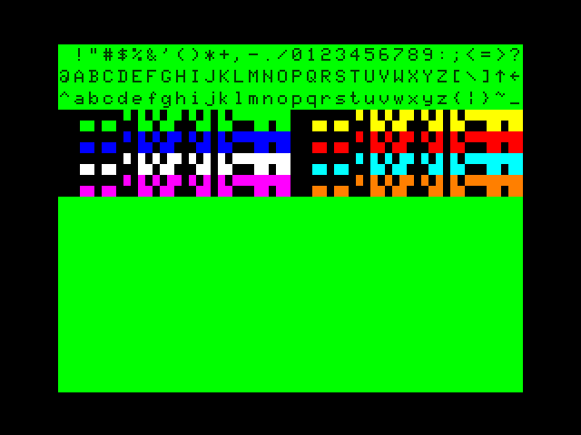
8 colors would leave two bits left over; for "blink" all you need is some signal that goes at a suitable rate, maybe 1-2hz. Don't know what to use the extra bit for, but I'm sure there must be something useful.

Another approach to the colour RAM, probably simplest of all, is to simply assign it to the top 1KB of the Z80s address space. OK, this would steal a whole kilobyte from the 48KB of system RAM, but how often does one sit down and type in a program that big? To prevent read contentions I would properly decode the RAM addressing so that the colour RAM properly substitutes the top 1KB of system RAM in physical hardware and does not mirror it, but the system wouldn't know the difference. "PRINT MEM" will still return "48340" and I'd still physically have a machine with 48KB of effective system RAM. Using the top 1KB of memory for program storage will just result in some funky psychedelic colour effects on screen!

Here's a lame idea: Have the effective base memory address of your color RAM determined by the contents of an 8 bit latch; if it's 1K then use 6 bits for the base offset and the other two bits to control something like if color is enabled or not. The color RAM itself is set up so it's essentially write-only from the CPU, but it can *mirror* any other memory in the system. For programs you want to use color in you decide where you want the color memory to reside and you write the offset and enable into the latch. If you don't *care* about being able to directly read color RAM you can stick it behind the keyboard or ROM; if you want to *effectively* be able to read it map it behind a reserved area in the normal 48k of RAM. In that case reads will *technically* come from the RAM that you stuck it behind, not the actual color RAM itself, but that'll work just fine.

(I vaguely recall a high-resolution graphics mod by... Dennis Bathory Kitz(?), that effectively worked this way, IE, the high-res memory was write-only but if you had an expansion interface you could map it "behind" upper memory and make it readable by having the graphics screen shadow real RAM.)

Having the colour RAM mirror part of the ROM is a possible alternative option, but only in my view if the Model III BASIC operating system permits POKEs to the ROM area. For some reason I was under the impression that it doesn't, but I might be mistaken. Can anyone chime in here?

So far as I'm aware there is no such limitation. I think there were versions of BASIC (first version for the commodore PET?) that tried to prevent you from *PEEK*-ing BASIC, but I'm not sure what the logic would be for preventing a poke.
 
You can do RGBI with a not-much-more sophisticated resistor ladder, as long as you're happy with not-bright-yellow being a weird greenish color instead of that brown CGA monitors tweak it to.

OK, but that is a "halfbrite" mode rather than a true 16-colour palette. Sticking to 8 colours still significantly simplifies my discrete logic video hardware (which has to fit completely on a eurocard) because it doesn't require any sort of ladder DAC for primary colour amplitude control in either the luminance path or the parallel chrominance path. In the former the primaries are simply either logic-high or logic-low and directly drive a simple luminance matrix. In the latter the primaries just on/off gate the quadrature U/-U, V/-V chroma carrier clocks (derived from a 4*fc oscillator) as required for simple vector addition.

In a previous life the AD722 was one of my favorite parts for composite video generation, but that part and ones like it are now long obsolete and building an example of whizz-bang video generation hardware with specialty chips isn't what my enhanced TRS-80 Model III hardware clone is all about!

... it's basically what you get with the Tandy Color Computer,

Yep. This is basically the look I aiming for (though there won't be orange):

Coco2bvdg_lc.png


I'm not open to complicating the design beyond 3-bit colour for reasons outlined, but I if I go for 1KB of colour RAM instead of just 512 bytes in the mirrored keyboard address area, I will make the character background programmable as that will only require the addition of a 74HC157 MUX to replace three AND gates.

So far as I'm aware there is no such limitation. I think there were versions of BASIC (first version for the commodore PET?) that tried to prevent you from *PEEK*-ing BASIC, but I'm not sure what the logic would be for preventing a poke.

I guess to be 100% sure one would have to probe the Z80 control lines to see if it is doing a phantom write when POKEing to ROM. I do want to be able to read the colour RAM, which will have to be found a workaround if it is to mirror the ROM area.

Alternatively, I could MUX the video RAM control lines with that of the colour RAM. The MUX select line could be controlled by a I/O port-controlled register bit. The downside to this of course would be having to toggle this register bit before and after every colour RAM read or write.

Lots of options to ponder over here while I log off to do some grocery shopping and tree pruning.....................
 
I guess to be 100% sure one would have to probe the Z80 control lines to see if it is doing a phantom write when POKEing to ROM. I do want to be able to read the colour RAM, which will have to be found a workaround if it is to mirror the ROM area.

I just double-checked to make sure and Level II/Model III BASIC has no problem at all PEEK-ing ROM, so I can't imagine why they would bother neutering POKE specifically so it can't poke to ROM. It's not like you could physically hurt anything with it. In a Model I in particular there's all kinds of havoc you can cause with POKE-ing outside of RAM and it definitely allows that.
 
OK, I just checked on my Model I Level II machine and POKEing to ROM doesn't throw up an "out of range" warning or some similar error message. I can't recall where I read that it would and I've never had need to check one way or the other until now.

Assuming now that POKEing to ROM isn't an issue, having to bank switch the system ROM for a colour RAM read is still an annoyance. You couldn't do this in BASIC as the interpreter is running from ROM. Colour RAM reads would have to be executed exclusively by machine code USR() routines resident in RAM. Alternatively, programs that require memory recall of colour RAM, such as for purposes of colour-based character collision detection or simply saving screen data to a data file would have to maintain a mirror of the colour RAM somewhere else in system RAM.

For these reasons, if I am not to use the keyboard block, I'd much rather appropriate a 1KB chunk of system RAM, but the issue that still needs to be investigated here is whether or not BASIC will corrupt my initialised colour RAM when booting. After hitting enter at the MEMORY SIZE? prompt, my Model 1 clone pauses considerably longer (proportionally as best as I can measure with my stopwatch) when the full 48KB of RAM is switched on/enabled than it does when only 16KB is switched in. The system is clearly doing some kind of memory check here which I assume involves incrementing through RAM at certian intervals and writing and reading back bytes.

I really have to get back into the garden now.
 
Back
Top