• Please review our updated Terms and Rules here

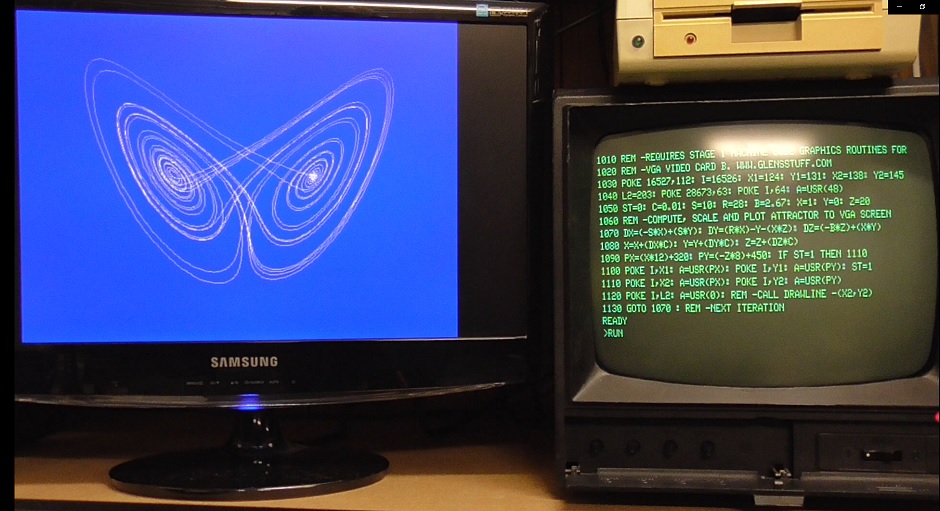
VGA graphics for the TRS-80 and others.

I think I have a better idea. I could use the power-on timer to set an IO port-controlled register bit which forces the address decoder to select an alternative ROM on start-up........

The more I think about this Frankenstein ROM-switching hardware scheme, the less enamored I am with it.

The Level III OS is full chock full of non-relative Jump instructions. For example a JP instruction to $3015 (the beginning of the boostrap/initialization routine) already begins at $0002.

The Keyboard memory space has four mirrors in the 1KB of RAM space partially decoded for it.

Lets say that I redesign the address decoding to assign the top-most keyboard mirror ($3B00-$3BFF) to ROM, effectively increasing ROM memory area by 256 bytes.

256 bytes is more than enough for a Colour RAM initialisation routine.

Lets say that I assign the top 1KB of RAM address space ($FC00-$FFFF) to Colour RAM. All things considered, I think this would be the least problematic area to poke the Colour RAM.

I then just need to find a JP instruction in the operating system ROM at an appropriate point at the conclusion of the bootstrap routine(s) and modify the address value bytes to $3B00 - the start of my extended ROM area and the 1st instruction of my custom Colour RAM initialisation routine. This routine would terminate and return the system to normal operation by simply executing a JP instruction having the address value that was modified in the original ROM.

I could even deal with the slight potential issue of having appropriated the top-most keyboard mirror. I could have an I/O port address register bit (just a flip flop), set on power-up by the power-on timer, which controls the address decoder to enable the ROM expansion. The ROM expansion becomes superfluous once the system has booted and keying in an instruction if required to reset this register bit would revert the keyboard address decoding to the standard mode of operation. So there I have a fix for the slight possibility of one day encountering some sloppily written program that uses the top-most keyboard mirror.
 
Last edited:
For example a JP instruction to $3015 (the beginning of the boostrap/initialization routine) already begins at $0002.

On the face of it this would seem the most convenient Jump instruction and point to modify to branch off to my Colour RAM initialisation routine, but at this stage I do not know if the memory testing routines that come later will write corrupting values to some locations of my Colour RAM.
 
Last edited:
Per my previous comment, if you don't like making the color RAM "movable" that's all right, but if you want it at the top of memory you could still have it "underlay" normal system RAM at the top, and you could use the contents of a latch (written by an OUT instruction) to control things like if writes to the color RAM were enabled, or if color is enabled, period. (Based on one of the bits the output circuitry would chose between the color RAM dictating foreground/background or a fixed white/black mapping.) If you had this then you could completely avoid compatibility issues with software that doesn't respect top-of-memory boundaries by simply setting the write-through-enable to "disabled" after the color RAM was initialized.

... thinking back to a previous comment, was this video system intended to be a VGA output or composite? The thread is about VGA output, but in the discussion about limiting the number of colors to eight chroma carriers are brought up. FWIW, the AD723 RGB to PAL/NTSC decoder is still in production. Seems to be kind of stupid expensive, though.
 
Last edited:
There's no check on POKE values so a POKE to ROM will result in the Z-80 writing there. Confirmed it with my emulator using trs80gp -m1 -dx -bm 0 which sets up a memory access breakpoint on location 0. A POKE 0,100 causes a breakpoint at $2CBB where it actually does the write.
 
Per my previous comment, if you don't like making the color RAM "movable" that's all right, but if you want it at the top of memory you could still have it "underlay" normal system RAM at the top, and you could use the contents of a latch (written by an OUT instruction) to control things like if writes to the color RAM were enabled, or if color is enabled, period. (Based on one of the bits the output circuitry would chose between the color RAM dictating foreground/background or a fixed white/black mapping.) If you had this then you could completely avoid compatibility issues with software that doesn't respect top-of-memory boundaries by simply setting the write-through-enable to "disabled" after the color RAM was initialized.

Yeah, that is already on the drawing board as mentioned previously:

To avert funky psychedelia I could add a colour RAM disable switch in the control of the address decoding to accommodate the possibility of encountering some commercial software that needs the full 48KB.

No Model I or III software was ever written to support characters in colour of course, so there is no disadvantage at all in typically having the colour capability switched off!

... thinking back to a previous comment, was this video system intended to be a VGA output or composite? The thread is about VGA output, but in the discussion about limiting the number of colors to eight chroma carriers are brought up.

The VGA card designs and the TRS-80 interfacing project were the original and then contentious topics of this thread. The original topic effectively died and was not successfully revived after I popped in to post a link to the completed documentation and exposition of the latter (not particularly surprising), but after Daniel initiated a discussion on the topic of high-speed Z80 systems this thread shifted to the topic of TRS-80 clone systems and my next project of working out the basis of another machine - an expandable, card-based Model III clone.

I resurrected this thread to continue the Model III clone design discourse on the issue of enhancing its native video generation hardware with the capability of colour:

I'm slowly getting back to this expandable Model III clone on and off in my spare time. I have abandoned the idea of using the S100 standard for this project and have come up with my own eurocard-based format.

I'm currently toying with the idea of enhancing the video generator with the option of basic color........

As per my previous TRS-80 clone and the original Radio Shack machines, this one when it eventuates will generate composite video.

As for my purely bitmap-based VGA card designs, they aren't and weren't presented as a replacement for a TRS-80s (or any other vinatge machines) stock video hardware, but an expansion port add on for plotting high-res graphics:

vgala.jpg
 
Last edited:
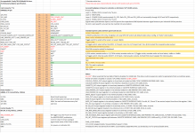
OK, here is where I am currently at in formulating the Model III clone colour specification. I think this is looking pretty compete and bug/issue-free now:


To fit the Colour RAM Initialisation Routine somewhere into ROM, without substituting any original functionality, the ROM area will be expanded by 256 bytes by appropriating the top-most mirror of the memory-mapped keyboard address space at $3B00-$3BFF.

This ROM expansion will be hardware-enabled by default, but the user will be able to disable it by resetting a control bit of a single-byte Colour Configuration Register located at a fixed I/O port address. This is just a measure to accommodate the slight possibility of one day finding software that uses the top-most keyboard mirror. Disabling will not present an issue as the ROM expansion does not have any utility after the computer has booted.

The Colour Configuration Register will have a second register bit, specifically for enabling/disabling the Colour RAM by properly bank switching (not merely mirroring!) it with the top 1KB of system RAM address space at $FC00-$FFFF.

The Colour Configuration Register, on the read side, will have an input of eight DIP switches. These will be read by the Colour RAM Initialisation Routine, permitting the user to effectively program the default colour configuration of the video display; the byte defined by these eight DIP switches will be written to all 1024 locations of the Colour RAM.

The Colour RAM Initialisation Routine will be branched to by modifying the address values of the very first ROM JP instruction starting at $0002. This means that the Colour RAM Initialisation Routine will be the very first thing the computer runs upon being powered on.

When the Colour RAM Initialisation Routine has written all 1024 bytes of the Colour RAM, it will set the bit of the Colour Configuration Register controlling the Colour RAM bank-switching to switch the Colour RAM out of circuit. The routine will then terminate by executing a JP instruction having the address value that was modified in the original ROM. From that point on the computer will boot as normal.

The computer will therefore boot with the initialised Colour RAM being disabled from CPU access by default. This measure will prevent the possibility of the Colour RAM being corrupted by the system memory testing routines that come later in the boot-up sequence, by user mistake, or by running any software that might utilise the top 1KB of system RAM.

To enable Colour RAM, the user will have to issue an OUT instruction to set the enable bit in the Colour Configuration Register.


Does that sound totally cromulent and foolproof?
 
This is currently a work in progress, liable to be amended as the design takes shape.....


bpv1.png
 
Back
Top