• Please review our updated Terms and Rules here

Vintage Computer Tools

Roj.

New Member
Joined
Oct 4, 2023
Messages
7
Hello VCFers

I'm a retired serviceman from the scientific instrument field.
I have a seldom used portable Hitachi V-509 CRO which I find, after a long period of dormancy, has a Ch2 vertical problem.
This CRO was seldom needed but always carried into the field so has done a lot of miles in my service vehicle and become dusty and cosmetically, a little wanting.
I can't recall how long ago I used 2 channels but it would have been years ago (I have a Kikusui 60MHz bench CRO so that the infrequent needs was supplied by it).

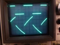
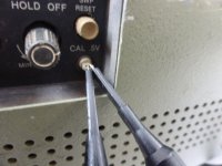
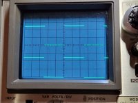
The attached waveforms are generated by the 0.5V square wave, in-built cal signal with a serviceable X1 probe connected to it and each channel.
Both channels are set to 0.2V/div
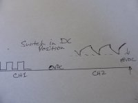
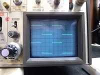
Ch1 (upper, squarish trace) is barely OK but Ch2 (lower trace) is unusable.

Save a couple of DVMs and the CROs, I have no test equipment, virtually none of that called upon by the Hitachi V-509 Service Manual.

I'm looking for any guidance before I take off the covers.

Thanks in anticipation.
Roj.
 

Attachments

  • P1070425.JPG
    P1070425.JPG
    139.5 KB · Views: 6
  • P1070427.JPG
    P1070427.JPG
    151 KB · Views: 6
Additionally, operating the AC/Gnd/DC switch of the faulty channel (Ch2) into the DC position, the trace 'sits' upon ~+8vDC rather than on 0vDC.

Ch1 behaves as expected.
 

Attachments

  • P1070428.JPG
    P1070428.JPG
    151 KB · Views: 2
  • Vertical Amplifier 2-rotated.pdf
    522.4 KB · Views: 5
Welcome

This is a very cool scope, I have yet to fix one of mine with a partial fault.
The problem with the crooked waveform, I had a similar one and had to clean a lot of mechanical contacts for it to go away. Does it behave differently when you exercise the vertical and horizontal sweep controls back and forth? Also check the BNC connector and probe for bad contacts.
The second issue, I've got no idea...
 
Thanks powerlot

No control, except the AC/DC switch has any unexpected action. Probes are OK, Ch 2 BNC maybe dodgy but I feel that's not all.

I omitted to say that I have an ESR meter and an Atlas semicon tester. The former may be a way to isolate a faulty electro.

Roj.
 
If you suspect the BNC connector you can bypass it and attach the input signal directly on the board (P102). There are some electrolytics but I don't know if they can cause this problem. The attenuator board looks like a pain to get out, I would try cleaning the switches and knobs related to CH2 first (especially since you mentioned the scope was in the field).

I could take some in circuit measurements for you, otherwise since CH1 is working you can compare the signals and see where it starts to deviate.

If you worked with scientific instruments I assume you're comfortable working inside an analog scope? Time to get in there... now that I'm looking at it again, I think I could have another go at my broken one.
 
Thanks powerlot

Covers are OFF
I'm employing my Kikusui CRO to compare the Hitachi Channels with the CAL signal applied to the inputs. CH1 is a reference of sorts (read on).

I've had mixed "results" (fault is now intermittent and can sometimes be induced by freezing of input components):

1. +/_ 8Vdc supplies found present
2. Found a significant Vdc difference at the gates of the input FETs:
"good" CH1, TR1, Vg = 650mVdc + noisy small square wave signal
"bad" CH2, TR101, Vg = 200mVdc + same noisy small square wave signal.
(Both Drains are 8Vdc, both Sources (1.3Vdc + small square wave))
3. using spray freeze on CH2 input stage was able to "fix" problem.
4. Voltages in 2. above, remain the same when no fault is present
5. Compared freezing effects on good CH1. This appeared more sensitive to freezing of a couple of spots. The same fault was NOT induced in this channel.
6. Fault returned during freeze application but unable to locate faulty device with certainty.
7. As might be expected, the components at the inputs of the FET and Op Amp stages seemed to produce the most DC reaction to freezing. Condensate on the pwb took time to dry and was probably contributing to the DC drift.
Freezing R120, R121, C123 produce the most dc shift and occasionally introduced or removed the fault. The FET and the TL071 OpAmp do not appear as sensitive to freezing.
8. There wasn't any consistency in what reintroduced the fault.
9. Removed Vert Preamp pwb, inspected and re-soldered all connections in the input area. Removed flux with IPA. Reconnected the pwb and the fault is NOT present. Will leave it to stew a while and give it the freeze treatment again in the morning (its 19:25, UT+8Hrs here).

Roj.
 
You've been busy... Did you also redo the boards with the BNC connectors? "the fault" refers to the waveform, the wrong DC offset or both?

Interested in your findings...
 
Hello powerlot

Yes, I reflowed the accessible connections on the little pwb that supports the ACDC switch. I wasn't game to reflow the wired connection to the rear of the BNC as I predicted too much work if the wire 'jumped'
away from the connector. There's too little space there!

Further thermal shock i.e. freeze at input cap C123 and resistor R120; causes a momentary -ve voltage shift after which the waveform assumes its previous, correct position.
Since the reflowing exercise, the freezer treatment causes both channels respond the same.
No heating or this freezing has caused the fault to reappear.
The CRO was on for several hours late yesterday and has been on all today and there has been no reversion to the CH2 fault condition.
Condition 2. above remains and is the only odd condition that I've found. This may have been pre-existing but it seems too odd not to be connected with the fault.
However, as long as CH2 remains normal, I'm not going to attempt sourcing parts or do any more (famous last words?).

Perhaps, when you get to fixing your CRO, you could check condition 2 and message me....?

Thanks for your interest and suggestions.

Roj.
 
Some pics:

No fault (CRO is still upside down to expose Vert preamp pwb).

Removing the case/chassis part which supports the front rubber feet improves access (2 screws)
 

Attachments

  • P1070429.JPG
    P1070429.JPG
    157 KB · Views: 3
  • P1070430.JPG
    P1070430.JPG
    167.5 KB · Views: 3
I took the "parts scope" which turned out to be the one that's working well and is in much better condition:
2. Found a significant Vdc difference at the gates of the input FETs:
"good" CH1, TR1, Vg = 650mVdc + noisy small square wave signal
"bad" CH2, TR101, Vg = 200mVdc + same noisy small square wave signal.
(Both Drains are 8Vdc, both Sources (1.3Vdc + small square wave))
On mine, Vg is 380-420mV DC on both channels (the difference being the square wave), otherwise similar to yours

Further thermal shock i.e. freeze at input cap C123 and resistor R120; causes a momentary -ve voltage shift after which the waveform assumes its previous, correct position.
Hitting these parts with freeze spray only caused them to shift for a little bit (maybe 1/8th of a division)... I only sprayed them for a brief moment though.

If it looks good to you I would say enjoy the scope, otherwise if you want to get to the bottom of this you could ask the resident expert in analogue circuits: @Hugo Holden , who was helping me fix mine a while ago
 

Attachments

  • v509-trace.jpg
    v509-trace.jpg
    338.5 KB · Views: 0
Everyone needs such "parts" equipment, powerlot!

Thanks for having a look at your CRO.
Your Vg measurements seem preferable for their sameness. Mine make no sense to me.
I was fairly dousing the input parts with Freezer and that drove either trace off-screen for an instant.
I will take any subsequent or repeat problems to the resident.

Thanks again and I hope you get at least one of you V-509s functioning.
(Now, back to re-aligning the sagged cones of a couple of JBL 12" speakers that need, and won't get it from me, expert attention.)

Roj.
 
Back
Top