• Please review our updated Terms and Rules here

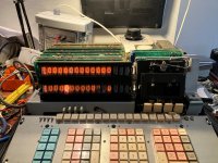
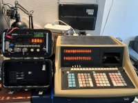
Wang Series 700B Advanced Programming Calculator Refurb.

Yes, superficially I'd assume the memory is working. There could be bits malfunctioning, but so far you don't seem to have any evidence of that.
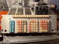
 
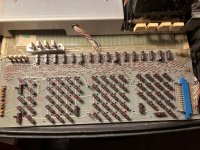
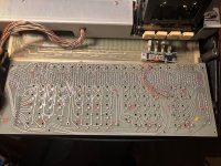
I took the keyboard out and apart to have a look inside, i quickly regretted that little idea. It's easy to take apart, but a hassle to reassemble. I do now know were that one screw i found underneath it came from.
The keyboard is a nice concept, all microswitched... quite pretty.

Keys.jpg

KeyboardF.jpg

KeyboardB.jpg

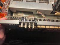
I find the wiring of the mode switches odd... the default "Run" button is only mechanicly linked to the other 3 modes, no wires/traces go to the switch.
ModeSwitch1.jpg
 
Yes, the mode switch wiring is counter-intuitive. The RUN switch really just serves as a mechanical release for the other switches. Those switches actually just drive the microcode branching instructions to cause the desired mode to be enabled, in other words they are just inputs to the microcode which cause it to take different paths through the "firmware".
 
Just a word of caution. These machines did not have very high MTBF. My high school had a Wang 520 - later upgraded to a Wang 600 - and I can't count all the times there was a serviceman working on it when I wanted to use it. And those servicemen no longer exist! I later bought two Wang 600's from Boeing Surplus, one of which worked (for awhile) and the other I never could get working (although I did not have the schematics, etc, that are available today). I would be careful just how much gratuitous disassembly I did - it might not run when you put it back together.

And, in spite of TTL not having a reputation for it, I would take all ESD precautions.
 
The mode switch is of a type that were very common in audio/stereo equipment as a selector.
If my memory is correct, there is a bar between them that releases the others when one is pressed.

For the tape drive belt, measure it and you may find a suitable one from a standard cassete deck.
The takeup reel may have a clutch which keeps a constant tension on the tape when playing.
Not always obvious as they can be built into the spindle.
If the tape motion is not smooth, this could be what needs attention.
 
This is really a great looking machine. What did they cost brand new back then? Curious. They can't have been cheap. But well made.
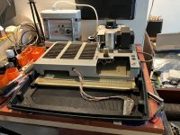
 
Chassis.jpg
Hmm, i believe i have come to the edge of what i dare to take apart. I'm not really sure how to continu from here without risking damage to either the cardbus or to where the cardbus connects to. All those cardslots are wired together with soldered connections. I'm afraid to break of one or more wires without knowing where it broke of from.
After taking the bolts out of the side, everything seems to still be very much stuck in place. I don't want to take the large PCB out in the bottom, as that is were this core ROM is located and i really don't want to mess with that.
I would have loved to take some pictures of that... but i don't want to risk it.

I feel it's a better play to shift my attention to the various cards, clean up all the edgeconnectors in the cardbus and the contactedges on the cards. Get the daughterboards in the PSU fixed (at least, change some of the obvious bad caps) and try to get as much of the old dust and dirt out of the machine as possible. Plus getting the tapedeck back into shape by cleaning and lubricating the mechanical bits and changing the belts.
 
For the tape drive belt, measure it and you may find a suitable one from a standard cassete deck.
The takeup reel may have a clutch which keeps a constant tension on the tape when playing.
Not always obvious as they can be built into the spindle.
If the tape motion is not smooth, this could be what needs attention.
Thank you, I still have to look at the tapedeck in detail so these are good points to take a look at. As for the motion, Rewind seems fairly smooth. Fast Forward is very jerky and Play was a little hard to see. But, as it's the same direction as FF, I suspect it's not smooth at all as well.

I have added a PDF version of my worksheet. It details (with photo's) the various cards and the positions of them within the machine plus some thoughts and comments for myself to keep track of what I find along the way. I will likely update this document along the way, probably adding things like Cap values and other possibly usefull info.
 

Attachments

  • Worksheet.zip
    5.4 MB · Views: 1
I also meant to mention that it is possible (but perhaps never been done before) to attach to the peripheral ports on the Wang. At the very least, a link to a modern "host" PC could be made via parallel port. The 24-pin connector is output-only, for the modified IBM selectrics (OutputWriters), but is otherwise very similar to the legacy "centronics printer ports". A program on a PC, listening for output from the Wang, could translate the codes to ASCII and do whatever you want. The Wang prints in "IBM Selectric tilt-rotate" codes, but those can be easily translated into ASCII. One could even imagine a small PCB with some logic and a PROM that translated to ASCII and passed the output along to a (more) modern printer.

The 36-pin connector is more complicated (8-bit bi-directional multi-device), but perhaps more interesting too. There are instructions (keys) for doing I/O to a wide variety of devices, including a mass storage device (fixed/floppy disk storage unit). I'm not aware of any software (that survived the ages) that uses these, but just from the keyboard you could save and restore chunks of program memory to/from the disk unit.
 
I don't know if you ever found these, I know I meant to send this link sooner. Here are the Wang schematics I used to build my simulators. It seems not every board in existence is represented here, but it is a start. Jim Battle has been another great source of information on Wangs.
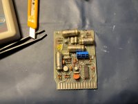
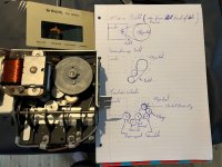
I had not found those, thank you very much for sharing.

I got a lot of information brochures about various Wang systems with my 700's documentation. It would be interesting to have things working on the I/O or output writers ports, I know there was even one of those large harddrive units available for the 700. Some of this stuff comes up on Ebay every now and again. There is a memory expension box for the 700 (with no extra memory in it) for sale right now. And the box that lets you connect to a Voltmeter as an Input (although that one is for the 600. Are things like that interchangable?).

When I look at the program sheets from the original user i get the feeling that my 700 was part of a larger system and that only the calculator and a portion of the tapes survived.
 
Regarding compatibility of peripherals between 500/600 series and 700, that will depend on the peripherals. Many of these peripherals, like the analog input (volt meter) ones, are issuing actual codes to the calculator, and the 500/600 series used different codes than the 700. They probably could be adapted to the other calculator, and with the schematics you have a chance of doing that. The memory and storage peripherals might be more universal, although I have not studied the 700 I/O protocols in-depth (I'd need to modify the simulator slightly and then go through the "Group X" and "I/O" instructions and see if they match the 600). From what I've see in that schematics doc, though, it appears each peripheral - even the "simple" OutputWriters - have different models and interface boards for 500/600 vs. 700. The differences may, or may not, be significant for a given type of peripheral.
 
I suspected that compatibility would be "maybe?" at best. Even though i can probably read and use the schematics for repairs, my knowledge on how this hardware works exactly is not very high. I also lack the equipment to properly monitor the output ports, or the knowledge to make heads or tails from any data that comes out of it.
 
I desoldered a few caps on the 2 daughterboard for the PSU and measured them. They all seem fine, capacitance values are within spec and the ESR is generally low. Even the cap with the crusty legs seems fine, but the corrosion means it has to go.

336-PSU-NewCap.jpg

I found some belts on ebay that should be the right dimensions for the drive, I doodled a little diagram that shows how the belts go in and how the rest of the drive works.

IMG_5836.jpg

At this point I'm going to start reassembly of the machine, the display, driver boards and PSU boards are back in. I just need to clean all the card edges and see if everything goes back together as planned.

I have also updated the document with the info on the tapedrive and the capacitors on the PSU cards.
 

Attachments

  • Worksheet-v2.zip
    6.1 MB · Views: 1
After all the card edges were cleaned I reassembled the machine and went for the smoke test. The machine was hooked back up to the Variac and the testbreaker box and I slowly increased the voltage. At first everything seemed O.K., the fan started spinning, the error lights would come on and go off again. Then, unexpected, a decimal point started glowing really early and as the machine came to life that one nixie tube got really bright, somewhat hot and the whole X line of the display didn't really work right. I could still do calculations and even perform the little program that had been in Core memory, but the display was not happy.

Bad.jpg

Turns out, one the legs of a transistor on the X display's driver card had come loose. It was never really soldered down properly and probably broke of while is was cleaning the cards. Crisis averted, hartrate back to normal... the machine works as it did before.

Good.jpg

Now i just have to wait for the belts for the tape drive.
 
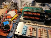
A little time has passed, the belts arrived and are now installed, the machine is also back together. Everything seems to work as it should... exept for the tape drive. I also had some fun with an old Fluke multimeter, using it to measure the voltage while slowly turning up the variac.

Fun.jpg

The new belts do make a big difference, the drive now runs very smoothly. Not really sure if the speed is correct, I also wouldn't know how to test it. But it seems the drive can't read anything on the tapes. I have little program at the start of memory that I wrote to the blank tape. That "Seems" to work, as in: it starts the tape and stops shortly after, flashing a "5" in the Y register and returns to a normal start state. After rewinding, when I try to load the program back into memory (doesn't seem to matter if I start at PC000 or at a random place in the Program counter) it does start the tape, but it never stops and it also doesn't load anything to memory.

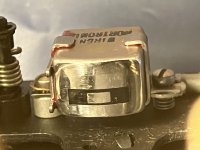
I did notice that the tape head seems to have some scuffmarks on it. I was not sure if this was a problem or not while taking the machine apart, But this is what the head looks like.

Tapehead.jpg

I'm now wondering how "standard" of a head this is and if I can just buy a replacement mono playback/record head for a tape deck from a home micro or something.
 
One thing you could try is to record a longer "program" (just put an EP at the last program step) and then playback the cassette on an audio player. You should be able to hear the recording (clicks and other sounds). That will tell you whether it is the record or playback that's failing (well, maybe not conclusively... will give you an idea at least). It sounds like when trying to load the program that the Wang never sees the start of data. That could be read head failure, but could also be a failure in the recording of the data, or even a failure in the data detection circuitry of the playback (i.e. might not have anything to do with the heads).
To some degree, if you are not trying to read tapes from other machines (or the Wang library), it doesn't much matter about the head, as long as it is a good mechanical and electrical fit. I'm not at all familiar with the details of tape heads, but I imagine there are variations in things like "sensitivity" and the like which might matter. The head would need to be electrically compatible with the record/playback circuitry of the Wang, but that might be a fairly wide net. There may be some markings on the head that might help. You could dig through the schematics to see if you can find values or part numbers (but I'm not optimistic). It might be important to match it with a tape head from the same decade.

But, the head might not be the problem so maybe check out the electricals first. I did extract some details of the tape format here: http://wang700.durgadas.com/wang700docs/wang700arch.html#tape
 
Back
Top