• Please review our updated Terms and Rules here

Wang Series 700B Advanced Programming Calculator Refurb.

Mono tape heads are still available new.
The tricky part might be matching the mounting, as there are many variations.
The resistance will be guesswork - usually around 100-300 ohms for cassette types, and you may need to modify the recording current 5k6 resistor for best results.
Looking through some ebay listings I thing the mounting is not that big of a problem. It seems to be the same as some generic mono audio cassette head sold for less then 10 euro's a piece. At that price i might just buy a few and see what happens. The only issue is I don't want to damage anything inside the calculator. Would using a tapehead with the wrong impedence from it's coil damage anything on the other end?
I have very little experience with tape systems, I've never used any home computer with a tape deck. I would hate to do something stupid and ruin this machine by using a cheap tape head...
 
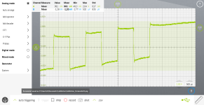
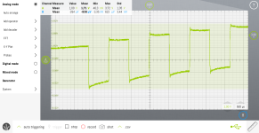
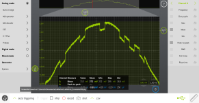
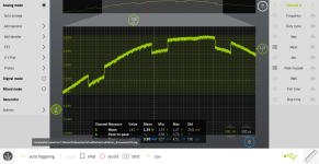
Well, nothing is coming out of the cassette tape adaptor (as expected). But, I was able to see that data is being send to the tape drive. I probed the connections of the head and got the following on one of 'm.
LabNation_Screenshot6.pngLabNation_Screenshot5.png

Now this was done by just putting the probe on the connection, I don't know if it looks correct... but it at least looks like data to me. It looks a bit funny, because I did not connect the ground clip to anything. Wasn't really sure where to put it and I was not searching for anything accurate.
 
The data format is a constant stream of clock pulses, with possible data pulses between them. So a clock pulse is following by either a data pulse or a gap, depending on if the data is "1" or "0". The "distance" between two clock pulses should be 4x the pulse width, measured leading-edge to leading-edge. The cleanest signal would be from dumping all program steps with memory zeroed, which is not so easy when you have core memory. We used to use a small program to clear all of memory, on the 600 this was done by storing "0.0" in all indirect registers - running until you store "0.0" over the program itself and "crashing". I'm not sure how well that works on the 700, as the codes are different such that "0.0" is not 00 00 00 00 00...

Unfortunately, the signal won't have any obvious delimiter at byte boundaries, and each byte is 9 bits (8 data + 1 parity). It should look something like the "record head signal" shown here: http://wang700.durgadas.com/wang700docs/wang700arch.html#tape , which your traces do resemble.
 
Looking at the signal on your website, I noticed something was up with what i was seeing this morning. Might be nothing, but i powered up the 700 again and put a 0 in the first 200 program steps followed by an end program, put a blank tape in and attached the scope to see the incoming datastream.

LabNation_Screenshot20.png
LabNation_Screenshot19.png

On the 700, the code for a "0" is "07 00", the data stream that I get seems to be inverted from the data stream you show on your website.
Did the same for "9" (which is 07 09) and got this.

LabNation_Screenshot22.png

At least they are clearly repeating patterns.
 
Yes, those signals look correct. The polarity will depend on where and how you attached the scope probe, and my diagrams are not based on actual observations but tracing of the microcode extrapolated to waveforms.

The problem of how to clear memory got me thinking, and so I tried it out on my simulator. Because of the way the 700 stores registers in program steps, I don't think it is possible to completely clear all of memory without some manual steps. I ran this program:

Code:
 0000   04 08  MARK
 000l   07 00  E0
 0002   07 l5  CLEAR X
 0003   05 04  ST INDIR
 0004   07 0l  E1
 0005   06 00  +
 0006   04 07  SEARCH
 0007   07 00  E0

and (as expected) it "crashes" on the last (almost) register. The problem is that the 700 stores one register in half of 16 program steps. So, when it stores that last-1 register it trashes the high bits of the program. On the 600, where a register is stored in 8 program steps, a similar program ends after clearing all program steps. But on the 700, the first 16 programs steps will be left only partially cleared. The user would have to manually clear the last register (or first 16 program steps).
 
Yes, those signals look correct. The polarity will depend on where and how you attached the scope probe, and my diagrams are not based on actual observations but tracing of the microcode extrapolated to waveforms.

Ok, that is good to know. I've been typing in 100 steps of 04 00, 05 00, 06 00 and 07 00 to see what sort of datastream would come out. Doing so I can kinda see where the first bit of a code is.

I think I'll just try to order some mono tape heads and see if that will work. If I have a working tape head it would be easy to measure the current it gets. I'll just order a few in the case something else is wrong.

As for where I'm probing the singal, on the right connection of the head. So that I could confirm for myself that the signal reaches the head.

probe.jpg
 
...
I think I'll just try to order some mono tape heads and see if that will work. If I have a working tape head it would be easy to measure the current it gets. I'll just order a few in the case something else is wrong.
...
I was suggesting trying a resistor first so that you can measure the current and have some idea whether it is exceeding a safe threshold. Of course, we don't know what that threshold is nor whether it will apply to the replacement heads. And, we don't have any idea what value resistor to use, unless we can measure the resistance of a working Wang original tape head. It is true that impedance is not the same resistance, and pulses into the head will behave differently than D.C. But the head's coil has a maximum safe D.C current limit, and I suspect the pulses should never be exceeding that.
 
My thought process being that something had to burn out the original head. If that was something like a shorted transistor, then the problem still exists and will impact any replacement head. The other possibility is that it was some sort of event, like ESD, and so as long as you don't repeat that event then the new head will work fine.
 
Yes, I understand. But the heads i found on Ebay have to come from China, which will take a while. I could still put a resistor of around the same value as the replacements to see what current is send through it.

I've ordered 2 different heads, 1 is a pack of 3 with an impedance of around 120 ohms (according to the seller). The other has no data on the sellers page but does state a model number so maybe a datasheet is out there with it's impedance listed. Datasheets may also show what the max. current is for these heads.

Also, I've tried to find some specs on the head that is in the machine now, but haven't found much. It's made by Nortronics and searching for them with the type number on it gives me a modern companies torque wrench.

There are some websites that have info on old Nortronics tape heads but they made a whole load of different types for all sorts of tape systems back in the 60's and 70's. I have not found one that matches the labels on the one in mine.

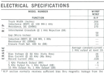
As is often the case, I start searching for the datasheet on 1 thing and find something different that is good to know. This is from a catalog from Nortronics. The model number in the Wang 700B's tape drive is W1R6N instead of F. It at least has some specs for head. This is from a document on Bitsavers.
Head-Datasheet.png
 
Last edited:
I tried putting a 220ohm resistor in place of the head (this is about the resistance in the datasheet from earlier). When doing that there is no data visible anymore on the scope, just the sine wave I always seem to get. So I don't think I can really measure any current with a resistor as I don't see any signal to measure.
Going back to the head connected I get the same signals as before, so everything is still working as far as it did before.

On a plus side, I managed to get a tape deck working to listen to what is on the tapes. There is data on there, both a higher pitched sound and a low rumble. The blank tape I used during testing also has some of these sounds in the beginning of side A (which is where I was recording to) but it's really really faint, as in barely there. So some form of signal still bleeds through onto the tape, that's my theory anyway.

But, measuring the head with the scope while loading it doesn't seem to pick up any signal. Doesn't matter if I pick a tape with a strong data signal on it or the weak one from the blank tape.

I guess I'll just wait for the new heads to arrive and continu testing after that.

I have been playing with the emulator @durgadas311 made, also wrote down the listings for the countdown and temperature conversion programs and typed them into my 700B. And they work great. Quite fun seeing it do something to be honest.
 
If you get no signal with a resistor in place of the head, that may be pointing to whatever caused the head to burn out in the first place. You measured the head as being an open-circuit, which means your observed signals were voltage only - no current. With a load, those signals are going to be much smaller voltage, especially with a 6.4K resistor in series. If the circuit drives 12V for record, then you'd see only 0.4V across the 220 ohm resistor. You'd certainly need to re-adjust your scope for that.
 
Oh god... do I feel like an idiot... as I should have known that (given what I do for a living...). Not that I use a scope for work, but it's basic stuff as an electrician.
I'll give it another go.
 
If you get no signal with a resistor in place of the head, that may be pointing to whatever caused the head to burn out in the first place. You measured the head as being an open-circuit, which means your observed signals were voltage only - no current. With a load, those signals are going to be much smaller voltage, especially with a 6.4K resistor in series. If the circuit drives 12V for record, then you'd see only 0.4V across the 220 ohm resistor. You'd certainly need to re-adjust your scope for that.
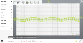
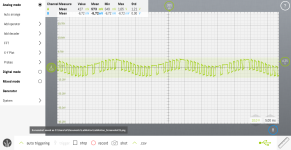
You were right, the signals are still there, just buried in a mountain of noise. I've tried to connect the ground clip for the probe to various metal parts of the inner structure of the machine but the noise always remains. The biggest thing i'd like filtered out is the 50Hz from the mains (I think this is the wavieness in the signals I posted before). This is why it's very hard now to find the actual signal, but at least I now know it's there.

They look like this...
LabNation_Screenshot37.png

LabNation_Screenshot34.png

So, the signal voltage is indeed around 0,4V to 0,5V. Which should mean that the current is between 1,8mA and 2,3mA (if my math is correct).
 
So, does your current computation look within the realm of "acceptable" for the old and new heads?
 
To eliminate the 50Hz noise, I think you should connect the *probe* ground to MHG. That's assuming your scope isolates that from chassis ground, which I would expect it does.
 
So, does your current computation look within the realm of "acceptable" for the old and new heads?
Well, that is going to be up in the air until I have the new heads. Tape is really not something i know much about, so no clue if around 2mA is good or bad. From an energy standpoint, 2,3mA at 0,5V is not a lot, 1,15mW, I can't imagine that it burns out the coil of the head to be honest.

Given there is an inductive aspect to the head aswell, and I'm not sure how big the impact of that is... we'll see. I bought spares so I have room for experimentation.

Also, while I was reading about replacing tape heads in some old documents. The coil does wear down with use and becomes less sensitive/powerfull.
Given that mine seems to have some damage to the head, maybe the coil got damaged and is open because of that. A component tester claims that the head is a tiny capacitor, which would make a little sense (to me at least) as instead of a coil it is now a stack of plates.

To eliminate the 50Hz noise, I think you should connect the *probe* ground to MHG. That's assuming your scope isolates that from chassis ground, which I would expect it does.
I don't know, this is a decade orso old USB scope that is hooked to a laptop. Not really sure if the ground connection on the probe is even really grounded to anything while connected to a laptop. The laptop is always powered from it's charger as the battery is long dead.
Would connecting it to my ESD worksurface have an effect (I'm a massive noob when it comes to scope opperation by the way, but also happy to learn more about it).
There are ground connections on the back of the scope but to my knowlegde those are used for the signal generator and the 8 bit analyzer.
 
Usually, a scope probe has it's own "ground", or perhaps better called the signal return. That does not mean it literally should be connected to ground, but rather that it needs to anchored to the "other side" of the circuit. That would be MHG in this case, which is the "common" connection for both MHO and WDT.
 
Back
Top