• Please review our updated Terms and Rules here

VECTREX WITH PROBLEMS

>>> Ok Dave but i connect to 0v of power or logic board?

Either.

Don't forget you can put resistors in series and/or parallel to make up other values you haven't got.

3.3k is only an approximation as well...

Dave
 
Dave, i realized a 3 kohm resistor with two resistors ;)
So these are measures:

WITH J402 CABLE DISCONNECTED AND WITHOUT RESISTOR:

IC304 PIN 6:
1,78 & -4,94 V

IC306 PIN 6:
1,66 & -2,20 V

WITH RESISTOR INSERTED IN J402 CABLE (BLUE X):

IC304 PIN 6:
1,74 & -4,94 V

IC306 PIN 6:
0,40 & -0,77 V

WITH RESISTOR INSERTED IN J402 CABLE (RED Y):

IC304 PIN 6:
1,74 & -4,94 V

IC306 PIN 6:
1,66 & -2,20 V
 
Excellent work that man :)!

This looks like that the fault is definitely associated with IC306 (or the surrounding circuitry) and clearly not related to the power board.

With the resistor connected to the blue cable, you can observe the output voltage from IC306 collapsing, whereas the voltage from IC304 doesn’t vary with the same resistor connected.

I suspect you need to order a replacement IC306. I will have another look at the circuitry around IC306 when I get back from my live streaming job...

Dave
Thanks so much Dave!
Electronics have no secrets for you! ;)

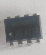
The other Vectrex I have to repair has only one MC34001 ... I could unsolder that and solder it on this console ... what do you think?
 
I can’t think of any other components (active or passive) around IC306 that could be causing the observed effect - other than a faulty IC306 component.

The only possibility is a high resistance / bad solder joint associated with the positive and/or negative power supply rails or the output pin. You can check this yourself using your multimeter on resistance (power OFF) and checking from the actual pin(s) of IC306 to the PCB tracking itself. The readings should be less than 1 Ohm.

I would buy a replacement MC34001 rather than desoldering one (from a working Vectrex) and using that.

Dave
 
Set potentiometers R401 (X SIZE) and R408 (Y SIZE) to approximately mid scale. This step is important...
At the moment this potentiometers are set to mid scale...when the console is up and running, will i be able to adjust them again?
 
I can find them on eBay UK. I am sure you should be able to find a few on eBay.it.

Just a word of warning, the MC34001 is a JFET part and is sensitive to damage by static electricity. You will need to use some antistatic precautions. Tinfoil is good...

Yes, we will use the diagnostic cartridge to adjust all the potentiometers when it is working.

Dave
 
Ok, thanks so much Dave!
After that I have another Vectrex to repair, remember? Can you help me with this too? Thanks to you, I am learning a lot and I am grateful to you! Remember to write me your address privately, it will be my pleasure to send you a small gift as promised!
 
Just unsoldered, easy job ;)
 

Attachments

  • Schermata 2022-03-20 alle 14.04.45.jpg
    Schermata 2022-03-20 alle 14.04.45.jpg
    116.7 KB · Views: 2
They look fine. Half the price of the UK ones to boot!

Let’s cross our fingers :)!

Let’s get this one repaired first and then we can have a look at the other one with the problematic controller.

We can also use the diagnostic cartridge on that one too.

Dave
 
Just a thought now you have removed IC306 as faulty.

You could connect the output pins (pin 6) of IC304 (the working in-circuit IC) and IC306 (the non-working out-of-circuit IC) together on the logic board.

This wouldn’t get you a working system though (just in case you were wondering)!

It would, however, check out the circuitry on the power board by connecting the Y signal to both the X and Y drive of the monitor.

You should now at least see images on both the left and right hand side of the screen - as well as the upper and lower half of the screen. This would be with the diagnostic cartridge in place.

Dave
 
With a small piece of wire?

Power up the vectrex (you should have a vertical line as there is no IC in IC306 to drive the X direction) and use a small piece of wire to bridge IC304 pin 6 (the IC that is present) and IC306 pin 6 (the IC that is not present).

It will be easier if you have an IC test clip or similar.

If course, 'waving' a piece of wire around may not be too clever if it shorts out somewhere...

You could follow the PCB tracking from IC304 pin 6 and IC306 pin 6 to some convenient point where you could temporarily solder a short piece of insulated wire. After the test, you can remove the temporary wire.

Dave
 
Ok Dave i undertand now! When i come back from my job i'll do this....but i think that today or tomorrow i should receive the new ic ;)
 
Hi Dave,
ic306 should arrive tomorrow (i hope), i tryied to connect ic304 pin 6 with ic306 pin 6 socket with a flying wire up on the pcb but
i can see only a diagonal line on the screen....In the meantime, I'm also working on your gift :)
 
The diagonal line is actually good :)!

Does it go from (approximately) the bottom left of the screen to the top right by any chance?

Photograph?

Dave
 
Excellent. That definitely indicates to me that the power board looks Ok.

If you remember, we were not getting any negative (left of centre) X deflection before. Now we do?

Dave
 
Back
Top