Worth noting that if you are dealing with open collector buffer IC's, you won't see anything on their outputs with the scope unless there is a pullup resistor. Looking at the card photo, the objects in the rectangular packages with the dots on one end are likely resistor arrays used as pullups, likely with the common connection tied to the + supply.
We're pretty sure that those are parallel resistor arrays. The mystery output we're seeing (assuming it isn't caused by odd aliasing) is a strange (relatively) low-frequency 5V p/p sawtooth wave.
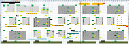
I looked at that "test your skill" board you linked - very nice, indeed they all seem to be oriented in the same direction
")
There are some white-color chips on the left side labeled BECKMAN - I feel like I've seen that brand somewhere, maybe in a Commodore system (maybe in the power connector internals)?
Those are DIPs but they are not chips: they're resistor packs. Of course, resistor pacts often have polarities too, and if they do, they should have a marking for Pin 1, just like an IC.
But then I noticed with good enough eyes, you can follow the traces on those boards. But right, once it crossed to the other side, then holding a probe on one side securely while searching the otherside wasn't the most graceful things to do (hunting 1 pin is fine, but scaling it up to reverse out the whole board is daunting)
With the Display Card circuit board, I'm pretty sure there's a lot more than what meets the eye: I think these boards have more than two layers. The traces you can see are helpful, but there may be others that are invisible. I think the only way to be sure that two components are connected or not is to measure between them. Luckily the components are all through-hole on the Display Card, so in theory you can do all of your probing work on the solder side, with the components facing the tabletop. It's still a major pain; no way around it.
Well... Like anything, one needs proper tools. My issue in soldering is I can glob together some metal - I did that for a quad I printed, wired up, and successfully flew. But for precise control, I often glob too much solder, spill over to another connector, and it's a huge mess to clean up. I've tried finer tips -- it's probably that I need more precise control on the temperature.
Practice, good equipment, and good materials are hard to find a substitute for --- unless you have a friend who can do the work for you. For some people, practice won't overcome hand tremors and the like, or they don't have time, or it's just hard; not much to be done. If you lived in London, I'd help...
I've realized I don't have to run those jumper wires from the inside of the A1 board - I could just use the pins on the backside (except some of those pins have so much wire-wrap already, even on the Display card, that there isn't much pin left to work with).
This strategy might work, but as you point out, it's really tricky. You want to make sure you have good connections, and you need to be certain that all 90+ are correct. Putting power into the wrong pin could be disastrous. Even just one weak connection could be hard to spot and might cause bizarre problems.
It would not be the hardest thing in the world to design an extender card based on the
substitute SLT plugs and sockets I designed. But it would be fiddly to put it together, and you'd still have the issue of holding the card extremely still: my connectors are more wobbly than the IBM originals.
I may pause here just to wait for the new (to me) oscope - and verify my D02 observations with that equipment (of the SAWTOOTH signal with the BAD Card, and nothing with the GOOD Card). Meanwhile, I may physically trace (as far as I can) both pin 3 and 4 on that chip.
I think this could be a good decision. Having dependable measurements will help us make good choices about next steps.
And just to throw this out there - what about the IR camera? For example, take PIN3 in the above image. If I let the board completely cool (i.e. take it out of the system for a day or two), then if I just apply 5V to PIN3 -- won't just the parts of the board connected to it warm up? And would it be enough of a difference to observe on the IR camera? Might not even need 5V - say just start with 1V? 2V? just that, I don't have super high resolution on the IR camera, so it may be too ambiguous - or I'd have to leave that voltage for quite awhile as I pan the camera around.
Let's consider this option. This will take a little while, but I think it might be worth reading. Physics lets us run this experiment in our head before we try it on sensitive hardware, provided you do the maths right. Knowledge is power... did someone say power?
Heat comes from power. Forget that the chip is a chip, let's assume it's just a resistor. You want to turn electrical power into heat, and that's what resistors do. If all you care about is heat, anything that conducts is a resistor, and things that conduct only marginally --- like
semiconductors --- are even better at getting hot.
What value should the resistor be? Well, the input to a driver IC is designed to be sensitive: it's not meant to demand a lot of power from the signal going into it --- after all, it's kind-of like an amplifier. It wants to turn a weak digital signal into a strong one. "Not meant to demand a lot of power" is in this case like saying it has a high resistance, or a high impedance to use a familiar term. You might want to think of this pin as a sensitive voltage sensor. Your voltmeter is also a sensitive, high-impedance voltage sensor for the same reason: it's not supposed to affect the circuit it's measuring very much. That also means the same thing as "not meant to demand a lot of power from the signal." All the same general idea.
So our thought experiment has to use a fairly high-value resistor to emulate the chip. Let's say
500Kohm. I could be off by an order of magnitude, who knows. 500K, got it, let's set that aside.
OK, you want to heat an IC DIP; that's a chunk of plastic.
How much energy do you need? Well, a plastic chip is, what, a gram maybe? I'm from America, who knows. It's probably a couple grams; let's just say a gram. Let's say you need to raise the temperature of the gram of plastic by ten degrees celsius for your thermal camera to pick it up. We can use the
specific heat of the plastic material to calculate an amount of energy.
This page says that plastics have a specific heat of around 1000 joules per kilogram per degree c. You've got a .001 Kg chip that you want to raise by 10 degrees c, so that's .001 * 10 * 1000 =
10 joules. (We're assuming that you only try to heat one DIP and that none of the energy manages to escape the chip, which are simplifying assumptions that are kind to you.)
Energy is power times time, so
how much power do you need and for how long? Well, you can't just trickle a low current in very slowly, since then you really will have to worry about the heat leaking out of your chip, and you may not get it to heat up at all. So let's say you only want to juice the chip for one minute to pump in those ten joules:
sixty seconds. 10 joules divided by 60 seconds is .166 W =
166 milliwatts, and you may start to sense a bit of a problem at this point. Let's press on:
We have the information we need now to compute
how many amps you'll be pushing into this pin, since power is current squared times resistance. Do a little algebra and: current = sqrt(power / resistance) = sqrt(.166 / 500000) = .00058 A =
six hundred microamps. Hey, that doesn't sound too bad, does it? Hardly any current at all.
Well, the problem is that 500 Kohm is a pretty slender straw to push 600 uA through. You're going to need to push pretty hard. How hard? Ohm's law says V = current * resistance = .00058 * 500000 =
290 V. That is probably not very healthy for a sensitive voltage detector that was never designed to see more than +6V or so on its inputs.
Now remember that you're interested in heating up more than one chip to detect continuity, and you'll also want to work in the real world and not this spherical cow world where the chips can never cool down. So, you'll need more power and more voltage in real life than what we've calculated here. In any case, I would not advise pursuing this approach.
BTW - I'm motivated to solve this because... One thing on my to-do list is to just emulate the entire Tape Control Card behavior. Forget the physical tape parts, the system just cares about the Data In and Out from the Tape Control Card. So the learning being done here hopefully applies to figuring out the tape stuff later (except it has some 12V pins that may make it "interesting"). But that's for the future
I'm glad you're pushing ahead with this and hope that my long messages have been helpful. Even though I've been long-winded and didactic, I'm learning a lot too thanks to your brave explorations. I'm keeping hopeful that we'll work out a fix, and even if we don't, there's still more to learn...