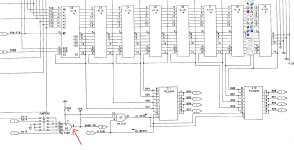
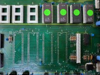
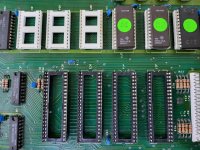
OK, got new 7425 chips........
But let me recap a bit to hopefully keep a clean story if someone needs to follow in the future:
.
A 2001N dynamic board that would show the initial random characters display (as expected) but will not boot. Followed the following testing method:
.
1. All the standard initial checks like voltages, clock, reset, IRQ and general prodding around to see if there's activity on the busses and control signals.
.
2. With that looking OK, installed a RAM/ROM board (with all the ROMs and IO chips removed) and found the machine will boot into BASIC4 with the RAM and ROM swapped out.
(*Side note: BASIC2 needs the 6522 to boot to the BASIC screen - be aware of this if you are using BASIC2 when fault finding).
.
At this point, it looked a sure thing that there's some fault in the main RAM which is not unexpected. 4116s are notoriously unreliable.
.
3. For the next test, I installed a NOP Generator and traced through the various busses, address decoding, etc. and this looked good from initial tests.
.
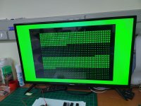
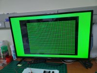
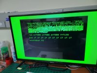
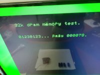
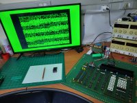
4. Now it was time to run PETTESTER. With V4 running (from either the Edit ROM socket or in the RAM/ROM replacement board), the test would get stuck on the VDU Test. I.e. the test output is visible on the screen but the test never concludes, it just sits here:
.
NOTE: Even with the main RAM swapped out, PETTESTER would still loop. Not unexpected, as it *should* not be affected by main RAM failures.
.
As @daver2 pointed out early in this thread, this looping implies that the display memory is returning a different value to what is being read. Or possibly that the CPU hangs. By looking at pin-7, it was clear the CPU was running, so it's likely something on the read path.
The display looked very stable (i.e. not changing characters, etc.) but it easily could be a stuck bit somewhere in the 2114s that does not give a visual artifact. And 2114s are notorious for being bad after 40 years. Tracing through the data (and address bus) paths show no obvious problem, but trying to fault-find buffers is not easy with a scope as the signals goes both ways.
- At this point, my best hypothesis was to suspect the display 2114s as they have a near 100% guilty conviction rate is all my previous PET repairs. So socketed them and tested. For once they were fine......rats
.
I then switched to another diagnostic tool to get a second opinion, so to speak.
.
5. I installed a PET Diagnostics device which is a small uP controller that sits in the 6502 socket and effectively test all the hardware, especially the RAM and ROM.
.
The screen output showed a clean display (i.e. all characters displayed were correct) and the display memory (8000) passed read/write testing. All the ROMs were also detected correctly with the correct checksums. However, a lot of the main memory showed errors. Looping the tests, showed consistent errors.
.
NOTE: In theory, bad main RAM should not affect PETTESTER but the fact that you need to swap out the RAM to boot into BASIC + the uP showed RAM errors, made me decide to get that sorted sooner rather than later. The uP test showed numerous errors, various bits in different banks failing, so I made an "aesthetics" decision to socket all of the RAM so the board looks like it came out the factory that way, i.e. did not wants a splattering of sockets in the RAM section. Tested the extracted 4116s in my external tester and most were faulty. Ended up replacing all 16 with known working ones to rather remove any doubt in that section.
.
6. With the main RAM sorted, I reran some of the tests and found that 1) BASIC still won't boot if the main RAM is not swapped out and 2) PETTESTER is still looping the VDU test and 3) the uP still randomly returns DRAM errors.
.
At this point I had confirmed a number of things that seemed contradictory in certain cases:
- Onboard ROMs are being decoded and read correctly (Kernal, PETTESTER runs fine) - So the data and address busses should be fine.
- (Replaced) VDU RAM passes uP tests, but PETTESTER is still not happy - seemingly contradictory.
- (Replaced ) DRAM still won't allow machine to boot BASIC, and gives random errors in uP test.
- NOP test (though crude) seemed to show working address decoding.
.
It looks like all the main elements are working, but they fail to run properly in different ways in different tests. All this seems to indicate that there is some control signal problem of some sort.
.
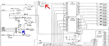
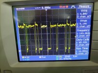
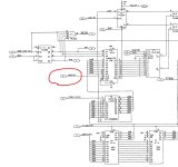
7. So (with PETTESTER running, still looping the VDU test), I started looking at various select signals, especially around the data and address buffers as we seem to have issues around reading/writing to memory. Most of the buffers showed what looked like acceptable timing and logic levels on pin-19 and pin-1, except E9 and E10, the two main data bus buffers:
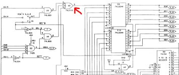
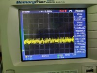
where this signal was present:
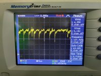
It did not look like any other buffer select signal and, for me, at least, did not 'look right' for what one would expect. The question now was who's at fault here. The 7410 itself or any of the 3 chips being driven by it? As the data buffers seems to work when the ROMs are being read, and the uP seems to be able to R/W memory, I suspected the 7410 itself - especially as all its inputs had valid looking signals - so socketed and replaced it. Unfortunately it made no difference and the extracted 7410 tested OK in an external tester. Bummer....
But then it's probably one of the inputs being driven by it. I then employed an old trick we used on fault-finding boards with soldered chips by carefully sniping the 3 input pins in such a way that they can be resoldered. This would essentially remove them from the 7410's output and I could see which one is causing the suspected issue.
Unfortunately is was none of them and even when I lifted the output from the NAND gate (by bending the relevant pin out the socket), I still got the same 'funny' signal.
Then, to add insult to injury, when I tried to tack the pins back, they were so badly corroded that it was basically impossible. Had to put 3 new chips in to feel comfortable about future reliability.
.
At this point in time, I retreated to go sulk over a few glasses of wine that 4 (all suspect to some level) working chips were replaced. And to rethink what I've missed in the testing procedure so far.
.
Second part of this post below.
But let me recap a bit to hopefully keep a clean story if someone needs to follow in the future:
.
A 2001N dynamic board that would show the initial random characters display (as expected) but will not boot. Followed the following testing method:
.
1. All the standard initial checks like voltages, clock, reset, IRQ and general prodding around to see if there's activity on the busses and control signals.
.
2. With that looking OK, installed a RAM/ROM board (with all the ROMs and IO chips removed) and found the machine will boot into BASIC4 with the RAM and ROM swapped out.
(*Side note: BASIC2 needs the 6522 to boot to the BASIC screen - be aware of this if you are using BASIC2 when fault finding).
.
At this point, it looked a sure thing that there's some fault in the main RAM which is not unexpected. 4116s are notoriously unreliable.
.
3. For the next test, I installed a NOP Generator and traced through the various busses, address decoding, etc. and this looked good from initial tests.
.
4. Now it was time to run PETTESTER. With V4 running (from either the Edit ROM socket or in the RAM/ROM replacement board), the test would get stuck on the VDU Test. I.e. the test output is visible on the screen but the test never concludes, it just sits here:

.
NOTE: Even with the main RAM swapped out, PETTESTER would still loop. Not unexpected, as it *should* not be affected by main RAM failures.
.
As @daver2 pointed out early in this thread, this looping implies that the display memory is returning a different value to what is being read. Or possibly that the CPU hangs. By looking at pin-7, it was clear the CPU was running, so it's likely something on the read path.
The display looked very stable (i.e. not changing characters, etc.) but it easily could be a stuck bit somewhere in the 2114s that does not give a visual artifact. And 2114s are notorious for being bad after 40 years. Tracing through the data (and address bus) paths show no obvious problem, but trying to fault-find buffers is not easy with a scope as the signals goes both ways.
- At this point, my best hypothesis was to suspect the display 2114s as they have a near 100% guilty conviction rate is all my previous PET repairs. So socketed them and tested. For once they were fine......rats
.
I then switched to another diagnostic tool to get a second opinion, so to speak.
.
5. I installed a PET Diagnostics device which is a small uP controller that sits in the 6502 socket and effectively test all the hardware, especially the RAM and ROM.
.
The screen output showed a clean display (i.e. all characters displayed were correct) and the display memory (8000) passed read/write testing. All the ROMs were also detected correctly with the correct checksums. However, a lot of the main memory showed errors. Looping the tests, showed consistent errors.
.
NOTE: In theory, bad main RAM should not affect PETTESTER but the fact that you need to swap out the RAM to boot into BASIC + the uP showed RAM errors, made me decide to get that sorted sooner rather than later. The uP test showed numerous errors, various bits in different banks failing, so I made an "aesthetics" decision to socket all of the RAM so the board looks like it came out the factory that way, i.e. did not wants a splattering of sockets in the RAM section. Tested the extracted 4116s in my external tester and most were faulty. Ended up replacing all 16 with known working ones to rather remove any doubt in that section.
.
6. With the main RAM sorted, I reran some of the tests and found that 1) BASIC still won't boot if the main RAM is not swapped out and 2) PETTESTER is still looping the VDU test and 3) the uP still randomly returns DRAM errors.
.
At this point I had confirmed a number of things that seemed contradictory in certain cases:
- Onboard ROMs are being decoded and read correctly (Kernal, PETTESTER runs fine) - So the data and address busses should be fine.
- (Replaced) VDU RAM passes uP tests, but PETTESTER is still not happy - seemingly contradictory.
- (Replaced ) DRAM still won't allow machine to boot BASIC, and gives random errors in uP test.
- NOP test (though crude) seemed to show working address decoding.
.
It looks like all the main elements are working, but they fail to run properly in different ways in different tests. All this seems to indicate that there is some control signal problem of some sort.
.
7. So (with PETTESTER running, still looping the VDU test), I started looking at various select signals, especially around the data and address buffers as we seem to have issues around reading/writing to memory. Most of the buffers showed what looked like acceptable timing and logic levels on pin-19 and pin-1, except E9 and E10, the two main data bus buffers:

where this signal was present:

It did not look like any other buffer select signal and, for me, at least, did not 'look right' for what one would expect. The question now was who's at fault here. The 7410 itself or any of the 3 chips being driven by it? As the data buffers seems to work when the ROMs are being read, and the uP seems to be able to R/W memory, I suspected the 7410 itself - especially as all its inputs had valid looking signals - so socketed and replaced it. Unfortunately it made no difference and the extracted 7410 tested OK in an external tester. Bummer....
But then it's probably one of the inputs being driven by it. I then employed an old trick we used on fault-finding boards with soldered chips by carefully sniping the 3 input pins in such a way that they can be resoldered. This would essentially remove them from the 7410's output and I could see which one is causing the suspected issue.
Unfortunately is was none of them and even when I lifted the output from the NAND gate (by bending the relevant pin out the socket), I still got the same 'funny' signal.
Then, to add insult to injury, when I tried to tack the pins back, they were so badly corroded that it was basically impossible. Had to put 3 new chips in to feel comfortable about future reliability.
.
At this point in time, I retreated to go sulk over a few glasses of wine that 4 (all suspect to some level) working chips were replaced. And to rethink what I've missed in the testing procedure so far.
.
Second part of this post below.

