fdiskitup
Experienced Member
That A12 line goes under the U11 and to a resistor, then on to the ram….
So I better connect it. Give me a min.
So I better connect it. Give me a min.
| VCF West | Aug 01 - 02 2025, | CHM, Mountain View, CA |
| VCF Midwest | Sep 13 - 14 2025, | Schaumburg, IL |
| VCF Montreal | Jan 24 - 25, 2026, | RMC Saint Jean, Montreal, Canada |
| VCF SoCal | Feb 14 - 15, 2026, | Hotel Fera, Orange CA |
| VCF Southwest | May 29 - 31, 2026, | Westin Dallas Fort Worth Airport |
| VCF Southeast | June, 2026 | Atlanta, GA |
Use TEST5077 from [here].If you can get a scope on A12 that would be good just to confirm you have a good logic signal. Wouldn't hurt to check others.
I just now brought out my motherboard. I checked U10 pin 26 again. I made a mistake. Like pin 27, pin 26 is connected to +5V. U10 pin 26 is not a concern to me. On both 2764 and 28C64 type chips, pin 26 is unused.As suggested, I checked all the PINS on the U10 (2764 Rom Bios Socket)
Everything is the same as the Modem7 board except,
"Pin 26 (not connected) has continuity to NOTHING. "
But on my board Pin 26 connects to U11, Pin 26 of "27256", and U13 Pin 14, and on the Flatpack somewhere in the Pin-7x's (counting anticlockwise from the dot, 30 pins, + 20 pins + 30 pins + 20 pins).
I didn't think I could see any connection to P8-1 on the power connector. That might also explain why rapid on-off-on produces some random results.BTW. Unintentionally, I discovered that this motherboard is of the type that does not use the POWER GOOD signal from the power supply.
The AT28C64 data sheet contains, "Endurance: 10,000 or 100,000 cycles"How many times can a EEPROM be reprogrammed ? my poor chip has been backwards and forwards.
I loaded up TEST5077 - it looks like it runs all the way through all 11's no 99's - then it loops back to the start counting up E0 to FF again.Use TEST5077 from [here].
It exercises all of the address lines to the 8KB ROM.
It does not not need the RAM to be functional.
It runs for about 2.5 minutes.
During TEST5077, the different address pins will have different signals, but they all change state at some point during the test.
For example, A12 is normally HIGH, and it will temporarily go LOW about every second.
For example, A6 is normally HIGH, and it will temporarily go LOW about every 2 seconds.
Verify that every ROM address pin is changing state.
( A logic probe is good to do this check. )
Excellent, but is that consistent? Lack of consistency has been a problem.I loaded up TEST5077 - it looks like it runs all the way through all 11's no 99's ...
A bug that I fixed yesterday. The latest TEST5077 will stop after [FF][11] is displayed.... then it loops back to the start counting up E0 to FF again.
yes, since I but in bodge wires it has been consistent - I added a switch to the power on off. Power on proceedure is now - (1) turn on psu integrated switch, (2) turn on the in line switch. This has helped with consistency, my guess is that without a true power good, the rise time of a cold boot psu is a little too long (?).Excellent, but is that consistent? Lack of consistency has been a problem.
A bug that I fixed yesterday. The latest TEST5077 will stop after [FF][11] is displayed.

A circuit diagram of the reset circuitry of my very-similar-to-yours motherboard is at [here].Power on procedure is now - (1) turn on psu integrated switch, (2) turn on the in line switch. This has helped with consistency, my guess is that without a true power good, the rise time of a cold boot psu is a little too long (?).
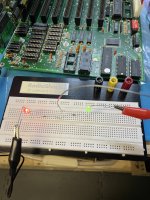
If the line is switching state very quickly, with roughly a 50%/50% ratio of HIGH/LOW, then both LED's will reduce in intensity. It is one of the reasons why logic probes have a 'pulse' LED.Some light up both dimly !
That's odd.And some lines dont flash!
That is a bad sign.the post card stops counting when I press down on the pin, but doesnt if I use the same pin in the adjacent socket (U11).
Sounds good.I’m going to stop here and remove both the corroded 28 pin sockets, examine the damage on the board. Fix the known issues (and get a real logic probe)
A high impedance scope probe should not impede the signals at all.The oscilloscope probe was also causing system hangs.
Note: The same channels that were behaving well with my logic probe also gave pulses on the scope.
