daver2
10k Member
I think you have probably answered your own question there!
Dave
Dave
Thanks - hiding in plain sight.>>> Also, what is VR3?
See post #82.
Dave
I got the cap kit from Allen of Ballyalley. After replacement, I now have +12v and no smoke. Also -5v. But +5v is coming up at zero. If I understand the schematic right the 5v comes from a ua78gu1c regulator. I have tested the pins.. the In pin is getting 22v. VOUT is -1v, and CONTROL is 0v. This would indicate either VR failure or a short (it is going into protection mode?). I've checked the RAM chips.. they have +12v at VDD and -5v at VBB and of course 0v at VCC. I'm not sure if these had a short if it would have shown the wrong voltage at VCC? I assume it would and the chips would fry?
C6 is showing +11.5vLet's do the simple thing first...
What is the unregulated DC voltage across capacitor C6?
This feeds the collector of Q1 and is the actual supply used for the +5V rail.
The control pin of VR3 is actually an INPUT to VR3. It measures the rail voltage and adjusts the output voltage (feeding the base of Q1) to control the sense pin of VR3 at +5V.
Dave
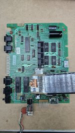
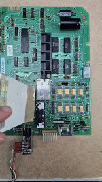
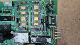
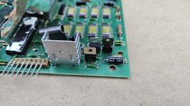
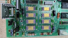
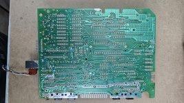
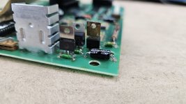
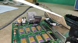
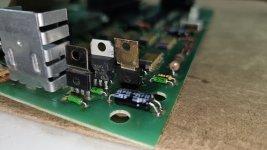
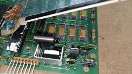
Attached.. hope I got enough detail.Can you post a good photograph of the top and bottom of the PCB showing VR3 and Q1 (and the surrounding components) please so I can trace the PSU schematic out by hand.
Dave
It's been a while but I'm pretty sure I tested +5v ok back in December when I was first probing about. But I was really focused on the 12v regulator that kept smoking up so not 100% on that.Did you ever have a correct reading for the +5V rail?