• Please review our updated Terms and Rules here

Bally Pro Arcade

falter

Veteran Member
Joined
Jan 22, 2011
Messages
6,580
Location
Vancouver, BC
Assuming this sort of qualifies as a computer since it is sort of programmable..

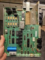
Apparently there was a glitch in the matrix this Christmas and my wife decided to feed my habit rather than try to save me from it. She got me a Bally Professional Arcade. Kind of a nice piece.. with original box, inserts, documentation, warranty cards, controllers and several carts including 2 BASIC carts and a couple of NIB carts. She got it from a local PlayNTrade, unfortunately they didn't test it and powering it doesn't seem to produce much. I'm going to check voltages etc.. I had read that a common cause of this is its custom data menu chip or whatever it is called.. nobody has produced a drop in replacement for this have they?

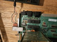
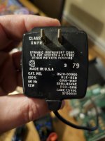
The PSU does seem to warm up. I didn't get smoke but there was a noticeable plastic smell from the cartridge port. Might be just be burning up dust.
 
Lucky you for the glitch in the matrix.
If I’m right it contains a Z80 CPU at 1.8MHz with video and sound so it is a computer.
If you can & if not done already archive the ROM contents as a protective measure.

Smell is not a good sign; hopefully it is benign or just an old cap.
Good luck!
 
So are we talking about the Bally Astrocade?
Yea. I hate that it has so many names. I did a bunch of reading and it seems like the most common cause of black screen is dead custom chips. Just checking out the PSU but so far so good.

I read the earlier units had a problem with overheating due to RF shield too.. maybe cooked itself. I just wanted to see if anyone had come up with replacements for the customs.
 
Did some testing with the ac adapter disconnected. I get 12.8vac instead of 11.75 and 9vac instead of 7.5vac. I am wondering if thst is due to the ac supply not being loader, or if that higher voltage has any detrimental effects with the rectifier and conversion to DC.

One thing I think may be a problem.. my PSU connector may have been installed upside down. The PSU changed a bit over the years but it looks like for mine it should be from closest to motherboard black, red, green and white. It was flipped the other way and there is evidence someone was messing around in here. Hoping everything isn't fried as a result.

The board itself looks alright.. nothing obviously broken or melted. Anyway, more reading.. once I'm confident the wires are connected correctly for my transformers wiring I'll try powering up again and see if I see any activity.
 

Attachments

  • 20231227_171638.jpg
    20231227_171638.jpg
    2.7 MB · Views: 14
  • 20231227_171659.jpg
    20231227_171659.jpg
    4.2 MB · Views: 14
Did some testing with the ac adapter disconnected. I get 12.8vac instead of 11.75 and 9vac instead of 7.5vac. I am wondering if thst is due to the ac supply not being loader, or if that higher voltage has any detrimental effects with the rectifier and conversion to DC.

One thing I think may be a problem.. my PSU connector may have been installed upside down. The PSU changed a bit over the years but it looks like for mine it should be from closest to motherboard black, red, green and white. It was flipped the other way and there is evidence someone was messing around in here. Hoping everything isn't fried as a result.

The board itself looks alright.. nothing obviously broken or melted. Anyway, more reading.. once I'm confident the wires are connected correctly for my transformers wiring I'll try powering up again and see if I see any activity.
I understand your concern. I’d independently test the power supply on a Load tester/Dummy Load to see if the voltages drop within range. Unloaded unregulated DC power supplies often have high no load voltages. Be aware that old tantalum capacitors have a tendency to explode, ignite or launch as fireballs so watch out!
 
I understand your concern. I’d independently test the power supply on a Load tester/Dummy Load to see if the voltages drop within range. Unloaded unregulated DC power supplies often have high no load voltages. Be aware that old tantalum capacitors have a tendency to explode, ignite or launch as fireballs so watch out!
Yep I have had several smurf grenades tossed at me and one actually came close to hitting my eye. Those little tantalums are impressive as IEDs.

Given that this transformer wall wart thing is putting out AC voltages is it better considered an AC supply?

I am just looking through every document I can find.. it seems like there were possibly 3 different ways these were wired.. the Bally way and then the 'Astrocade' way after the new owners tried to rectify problems.

They weren't kidding about the RF shield. It's any wonder these things cooked.
 
I did my best to research the power connector. I'm so used to DC. Anyway, the wall wart shows the attached. That means the 7.5vac is delivered via the inside two wires. This being AC, it therefore shouldn't matter if the connector is 'upside down', since flipping it over wouldnt change that.

Anyway I plugged it in again, this time I got a bit of smoke, I think it came from an LM342 regulator. At least, I think it did.. afterwards I'm questioning myself, because I can't easily make out any physical damage to components in the power supply section and there are a few regulators packed into that area. But pretty sure I know where it came from. I notice two of its pads on the PCB have broken loose.
 

Attachments

  • 20231227_210057.jpg
    20231227_210057.jpg
    1.1 MB · Views: 8
I'm the original owner of a Bally Astrocade - also currently not working.

Here is my photo of the adapter and corner of the board with the power connector.

Bally_Astrocade_adapter.JPEG

I do notice the AC voltage is a little lower than your 11.75 VAC at 10.8 VAC. And the date code on my adapter is 1982 but the Catalog number is 0620-00911

Here is the power supply connector section of the service manual

1703795880584.png
 
Last edited:
Interesting.. yes yours looks like mine. The date code on my adapter is 79.

I'm really weak on how power supplies work. I don't think regulators often fail and burn up on their own.. im guessing my issue is downstream. One problem I have is im not 100% sure where the smoke arose from. I'm pretty sure it was the 12v regulator, but there's no physical damage or signs of smoke, and that regular had a paper insulator around it. So now I'm doubting my memory, even though I recall seeing smoke wafting up from between the folds of the paper shield around that part.
 
Much obliged. That clears things up a fair bit. I'm curious how they drop the voltage to 10v with a 12v regulator..
 
I also have the 10.8/7.5V adapter. My two Astrocades are fortunately working fine.
Yeah I think this 12v regulator bit it.. althoughbso far testing from the power connector onwards I'm not seeing anything that would have shorted it out. When I just slightly bent it to look at the model number info, it broke right off. I think it had been overheating a while.
 
I have just been reading your thread.

There is something a bit strange with the PSU (in more ways than one).

+10V is clearly used by the custom ICs - so there must be a +10V supply from VR2.

As for VR1 (+15V) this is highly suspicious... This supply appears to be used by the DRAM chips (MK4096N according to the schematic - but they have a '*' by them and VR1). If you look at the data sheet for the MK4096N DRAM it requires +5V, -5V and +12V supplies. If you feed it with +15V instead of +12V you will destroy the DRAM...

So what DRAM devices have you fitted and what is VR1?

Dave
 
The two centre leads (RED/GREEN) should be approximately 7.5V AC - giving approximately 7.5 * 1.4 = 10.5V DC when full-wave rectified and smoothed feeding the +5V regulator (VR3 and Q1). A tad high for my liking - 8V to 9V DC would be my preferred.

The two outer leads (BLACK/WHITE) should e approximately 10.8V AC - giving approximately 10.8 * 1.4 = 15.2V DC when full-wave rectified and smoothed feeding VR4 (-5V) and VR1 / VR2. There may be a very low current consumption on these voltage regulators if they are only supplying the DRAMs and the custom ICs.

It is unlikely to have done any damage if the AC connector was accidentally reversed.

Dave
 
I have just been reading your thread.

There is something a bit strange with the PSU (in more ways than one).

+10V is clearly used by the custom ICs - so there must be a +10V supply from VR2.

As for VR1 (+15V) this is highly suspicious... This supply appears to be used by the DRAM chips (MK4096N according to the schematic - but they have a '*' by them and VR1). If you look at the data sheet for the MK4096N DRAM it requires +5V, -5V and +12V supplies. If you feed it with +15V instead of +12V you will destroy the DRAM...

So what DRAM devices have you fitted and what is VR1?

Dave
Thanks for offering your thoughts, Dave!

They don't have anything marked in silkscreen on the PCB and havent fully traced things out yet, but here are the four VRs I see:

UA78Gu1C
Lm342p 12
LM320MP 5.0
Lm342P 10

The RAM are MK4027P.

I guessed the AC connector was ok either way. I was pretty sure someone had been in here before. Although the RF shield appeared untouched/opened, there was a screw missing from the bottom. The AC XMFR connector was upside down vs all the pictures I'd seen of other units. Does it actually matter at all, given the higher voltage wires are on the outside of a 4 pin connector and the lower voltage inside? AC doesn't involve polarity does it? I would assume if not it doesn't matter which way it's oriented since the the higher +11.5v wires would still be connected to outside pins, and lower +7.5v to inner pins even upside down.

I'm trying to see if the dead 12v VR has crossover with TI parts? In the datasheet I see it reference a 7812 which I think is the TI part number equivalent? I have a few of those..

Also, is possible for a VR to fail on its own internally and smoke like that? Or is it usually due to something external (overvoltage, short etc). The datasheet refers to the LM342P as "indestructible".
 
Last edited:
Back
Top