• Please review our updated Terms and Rules here

Bally Pro Arcade

COMM would be short for COMMon in my mind, so I'd expect it to be ground. On a 7805 the pinout is usually I-C-O, for input-common-output, for instance.

If you can, I'd lift the input leg of the µA78G (datasheet, for everyone else) out of circuit and check continuity again, to see if the short goes away.
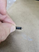
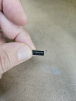
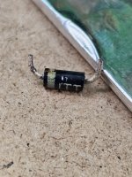
Actually, once removed it tested OK. It appears to be C8 being shorted that presents the "short" at VR3. It's one of those bullet shaped ones. Dave I think said it shouldn't be a problem I think. After removing it it definitely is shorted... hmm.
 
Last edited:
If you read my posts #44 and #46 correctly, I didn't say that a shorted C8 wouldn't be a problem (it will) but (being on the INPUT side of the regulators VR1, VR2 and VR3) it would NOT result in an increased current in the regulators - hence they should not smoke.

In fact, it would do the contrary, a shorted C8 would starve the regulators of current. As a result, the output voltage from all/some of the regulators could fall.

As a further fact, some of the PSU current would be diverted through C8, so the regulators would run cooler!

If anything, it could be C8 that smokes, or it could damage the rectifier diodes (that you have already checked as OK) or it could damage the transformer winding.

Dave
Ah.. I read what you wrote wrong.

Starving for current.. that could explain why the 7812 had so much trouble reaching +12v? But then why would it smoke?
 
Okay.. thinking.

The PSU is putting out more AC voltage than it should, but by +/- 2 volts for each of the two major voltages it supplies, even when loaded. Is that enough to cause a problem?

The rectifier diodes seem to check out ok.

When powered, only VR4 smokes. Why don't the others? Did I just get unlucky pilfering a bad VR from a rando piece of equipment? The board it came from was what appeared to a NOS PSU board of some kind from an industrial machine. Didn't look like it had ever been used. With the bad bullet cap removed, there's nothing shorted now that I can see.
 
>>> The PSU is putting out more AC voltage than it should, but by +/- 2 volts for each of the two major voltages it supplies, even when loaded. Is that enough to cause a problem?

Nope (unless something is operating right at - or just passed - the absolute maximum limit). Of course, this limit effectively falls with the equipment age. You can't run as fast or as far as you did at School can you...

Hang on a minute, we are talking about VR4 smoking here... C8 has nothing to do with VR4? VR4 is the -5V regulator isn't it?

You might like to read up on a few references for power supply unit basics. Every machine has one - so knowing about them is useful!


That will keep you busy for a while...

Dave
 
Last edited:
While I'm reading through all this (I've really learner a lot this week thanks to everyone here, especially Dave)

Is this 'bullet' cap anything special? Or can I just match the values and run. I think I make out: Kemet 6R8uF, 35v, 20% (tolerance). Any time I encounter something in an unfamiliar form I pause.

Just lining up a parts order, I know this isn't causing my issue but it is definitely needing to be replaced.
 

Attachments

  • 17044296861501787567650126846081.jpg
    17044296861501787567650126846081.jpg
    1.9 MB · Views: 10
  • 1704429713362746602947573818718.jpg
    1704429713362746602947573818718.jpg
    1.7 MB · Views: 10
6.8uF 35V. Ignore the tolerance...

I would say a polarised electrolytic or solid tantalum - with the leads arranged as per the original.

Just make sure you install the replacement the correct way around!

It looks to me as though C8 is in parallel with C1 (according to the PSU schematic). If you follow the positive (+) lead from C8 (on the PCB) it should run to the positive side if C1.

IF this is the case, the PSU should run (as a test) without C8...

Dave
 
Finally getting back to this. Question. I removed the last couple of diodes for the power supply. In the updated schematic someone did it says all 8 diodes are IN4007. However these diodes (1-4) look physically different. They only have ITT stamped on them though, so I'm not sure if they are in fact the same. The ones labeled 4007 are a bit smaller.
 

Attachments

  • 20240217_171907.jpg
    20240217_171907.jpg
    1.4 MB · Views: 6
Couple other things that aren't making sense to me.

The service manual shows CR1-8 are all same, 1N4004 diodes. But the updated schematic drawn by someone else shows 1N4007. Which is fine, the PIV of the 4007 is higher so I assume it doesn't matter which is there really.

But then the VRs.. I've gone back over it and am confused why I have a 7812 in the first place for VR1, when the schematic calls for a LM342P-15. All the other VRs I have on board match what the service manual says they should be except that one. I'm guessing at some point the circuit was revised and a 12 volt rather than 15 volt VR was subbed in? I've been through a few versions of the documentation though and haven't see anything that shows that to be the case..

I don't think the original Lm342p 12 was a replacement - it looks to have been original so..
 
Ah.. it appears Bally may have changed to a 12v at some point without updating their service manual. One place I found said it is common to find a 12v regulator at VR1 rather than 15v. Moving on!
 
As I stated back in post #18, an MK4027 DRAM is operated from +12V, +5V and -5V (nominal) supplies.

Running VDD at +15V instead of +12V = BANG!

Sometimes, things like this are deliberate...

Dave
 
Yes - I was thinking they might have used a zener or something to drop the voltage down to +12v but I couldn't find it on the schematic. It's weird that they left it as +15 in the service manual and schematic. And then that fellow that retraced the schematic here, if I read correctly went over his own board to do so - so I'm wondering if he actually saw a +15v regulator on his own board or not, since he again shows it as +15v.

Having gone through dozens of photos and sites it does seem like Bally varied a couple things on the motherboard over time, including the wall wart transformer.

Anyway, back to troubleshooting. Apart from the part number discrepancies, so far the real life board checks out against the schematic for the PSU posted in the service manual. Not finding any obvious shorts.. think I'll use the variac and try to get a handle on what the input and output voltages for all of the regulators are.. maybe there'll be a hint there.
 
Also, I've retested the diodes with my analog MM to verify my results. There is a single diode, CR4 I believe, that varies slightly from all the others. It is not a dead short, but it does have less
Remind me, what 'smoked' again?

Dave
The +12V (VR1). The first time I plugged the machine in, I got a nasty smell, and eventually found smoke coming out of the 7812. I installed another 7812 I had in my shop and tried again, this time testing voltage output (didn't get time to test input). Noticed it was at +10v and struggling its way up to +12v. Then it started smoking and output voltage collapsed.

That's when I started digging into the VRs because i was sure we must have a short there. But they all seem fine.. no resistance with my analog multimeter probes one way, very high resistance the other. One of them had slightly less.

Now that I have more 7812s, I'm thinking I'll look at the input side and see what's going on there.
 
I will put together a model of the PSU to see what should be going on.

The thing that is bugging me is the 0V reference for the +12V and -5V supplies. The only connection to 0V I can see is the common reference pins of the voltage regulators.

Dave
 
Putting together a model of the PSU is turning out to be more challenging than I first thought...

Question: On the input of VR1, is there a dropper resistor (like there is for VR2 - with R1)? Or is there just a wire link?

I am making the assumption that the transformer secondary winding between pins 1 and 4 (that go to the ON-OFF switch) is a plain old winding with NO centre tap (or anything smart) that goes anywhere else?

The issue I have is that the 0V reference for both the +12V supply (VR1) and the -5V supply (VR4) is at the COMMON connections of the two voltage regulators.

The +12V output of VR1 is relative to the common pin of VR1.

Likewise, the -5V output of VR4 is relative to the common pin of VR4.

However, the DC input voltage to both VR1 and VR4 is derived from (what is effectively) a floating supply formed from the transformer secondary and CR1, CR2, CR7 and CR8. The excess voltage has, therefore, to be dissipated across both VR1 and VR4 - but the exact proportions (and hence the power dissipation in each voltage regulator) is sort of undefined.

Just to remind you, the pinout for the negative regulator (VR4) is different to the positive regulators.

Still no further forwards...

Dave
There is a resistor connected to the input leg of VR1 for sure.

Side note: I was conversing with some bally alley folks and they said the kemet caps are complete garbage and recommended replacement with a cap kit that's available, not just for those but other caps. A fellow who repairs these boards all the time said about 95% of the time it's cap failure somewhere.

I'd still prefer to go at this methodically and understand how it works though - there are differences in the design of the Astrocade over the years.
 
I was going to post (and then forgot) that the classic failure mode would be a short circuit (or partially short circuit) capacitor.

Bizarrely, the capacitor on the input side of the -5V regulator is something I would check first! If this was short circuit, this would cause the maximum amount of voltage to be dropped across the +12V regulator, causing the maximum amount of power to be dissipated in the process.

However, a 'pucker' modern voltage regulator should just shutdown, not smoke...

Dave
I wonder if I just got lucky and had two bad regulators in a row. The second one, only one I had at the time, came from a rather old and sketch looking piece of equipment I had lying around.
 
Back
Top