• Please review our updated Terms and Rules here

Bally Pro Arcade

MK4027 DRAM requires +5V, +12V and -5V supplies. The +10V supply is for the custom ICs. This defines the voltages required from the regulators.

Correct, if you reverse the AC transformer windings it makes no difference (99.99% of the time) on a power supply. At least someone used their intelligence in ordering the connections on the connector. As a result, it should not matter in the slightest if the AC connector is reversed.

In general, a TI 7812 should be a direct replacement. Check the datasheets for the two regulators. Check the current rating and pinout. If these are the same, in general, you should be good to go.

Don't forget, if these devices are 35+ years old, the word "indestructible" doesn't actually apply anymore! Old semiconductors can have manufacturing issues over time. For example, IC pins rust the plastic encapsulation can let in water vapour over time, the epoxy used in the packaging can degrade and degrade/destroy the internal semiconductor, purple plague (look it up) can occur internally. All these issues kan 'kill' a device over time.

I would have said that a RIFA capacitor or a tantalum bead capacitor was "indestructible" (once it had passed its burn in process). You would disagree with that statement wouldn't you! But, if you look at the datasheets for the devices, they do not describe an end-of-life condition...

Indestructible voltage regulators are indestructible, until they destruct!

So, yes, a voltage regulator can self destruct...

Dave
Much appreciated Dave.

Yes I was once indestructible, but nearing 50 am not, so it figures these regulators would lose that characteristic with time.

So having checked out other components between the PSU connector and the smoked regulator and not seeing anything amiss (which we have to take with a grain of salt as I'm not always 100% with this), would the procedure be to swap in another regulator and see what happens?

I'm wondering too about the voltages coming off the ac adapter, which are 1-2 volts higher than each is supposed to be with the ac adapter disconnected from the motherboard. I'm hoping they're coming in high because the adapter is unloaded. Could a couple volts extra AC contribute to frying things down the line?
 
The voltage from an unloaded, raw transformer will generally be higher than rated. It also depends upon what the mains voltage is at your socket outlet as well. This will vary over time depending upon the time of day etc.

If the mains voltage is high, the output voltage will be proportionally high...

The potential extra Volts (when turned into DC) will have to be dropped across the regulator. So, yes, the regulator will run hotter than if the voltage is lower. Unfortunately, a fact of life...

Put in another regulator and see what happens.

Dumb question, do you have a Variac? If so, you can increase the AC mains input voltage slowly and measure things as the voltage increases in steps.

Dave
 
Yep! I bought a variable a while back. But it's a cheapo one off ebay (didn't realize at the time - rookie). But that should be fine?

One other question for you - given the Bally Arcade has 3 custom ICs that are unobtanium except from other Bally consoles, should I have those removed for testing? Or maybe already too late.. I'm not sure what happens when a VR burns..

As always, thanks Dave!
 
Cheapo one off eBay. Yep, rookie!

Do you have an earth leakage device you can use in the mains socket to ensure you make it to Christmas 2024!

It is probably too late now I am afraid to remove the custom silicon...

Dave
 
Last edited:
I don't have an earth leakage device - actually had never heard of those until today. Now will investigate.

I've been looking at the datasheets for the 12 volt regulators I have available vs the lm342p. The pinouts look the same, input/output voltages the same - I'm not really seeing any difference between LM342P-12 and UA7812 or LM340T-12. But there must be a difference somewhere right? Otherwise why the different model numbers? Amperage perhaps? I see the 342 can deliver about 0.25, whereas the 340 seems to do 1.0 amps+ ? Which is not a problem if the output current amperage on the replacement is greater?
 
Yes, I ALWAYS use an earth leakage trip or a residual current circuit breaker with anything I play with. That includes vintage computers, electric lawn mowers and hedge trimmers etc. One day it could save your life!

Correct, if the output current capability of the replacement is higher than that of the original that is not a problem, unless you have a short circuit somewhere on the output of the regulator. However, it is highly likely that the power supply ahead of the voltage regulator will limit before that...

Dave
 
Dave, are you talking about a Ground Fault Interrupter (GFI)?
images
 
If we're talking about GFI, I plug into one of those.

Also, I see now there is a physical difference between the LM340 and LM342. The plastic body is physically larger, which makes for a tight fit on the board with the LM320M close beside it.
 
I think we are talking about the same thing. It is perhaps called different things in different places.

The unit I have interrupts the live and neutral conductors if either a current > 30 mA flows in the safety earth or there is an imbalance of current in the live and neutral conductors (the difference must be flowing to earth somewhere) or the current flowing exceeds the rated limit.

Dave
 
I have installed a GFI outlet in a bathroom - is this what is being discussed? US code requires them for main outlets near any water source. See pdf here. I was not aware that you could get portable ones - I should probably get one for the work are.
 
I think that's GFCI over here, and I definitely have them in a few key places in the house. Most often they are installed outdoors, bathrooms and in garages/workshops. Maybe a difference in terminology between UK and USA. I watch a lot of British TV like Time Team and often have to pause and look up words or slang they use. Some of it has even leaked into my head and now I'm more likely to announce I 'nicked' a cupcake my wife made rather than 'stole' it. :)
 
Yes I'm very lucky she puts up with me. Otherwise I would be a hermit subsisting on ramen for sure. I was quite surprised she bought this Bally machine for me, she does have a tenuous relationship with my hobby and sometimes openly wonders about the miracles of compound interest if I just sold it all and invested the cash somewhere.

Now to.. ulp. Test the board. I'm going to put a camera on it to catch any smoke so I can be sure if I got the wrong device that I get it this time. But I'm pretty sure it was the 12V VR. It literaly snapped like a toothpick with the gentlest movement.
 
So no visible smoke with 30 sec plugged in.. but I did get a whiff of burnt plastic again. I just can't figure out where exactly it is.

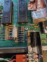
I need to review my diode testing procedures. I'm getting very different results when I check with my DMM on this row of 8 here. One of them (third from top) has zero resistance one way. All the others have at least some resistance one way and tons with the probes reversed. I'm not finding the diode testing mode helpful here.
 

Attachments

  • 20231230_142848.jpg
    20231230_142848.jpg
    1.8 MB · Views: 4
Can you identify which CRn it is (either from the PCB silk screen or the maintenance manual).

0 Ohms in one direction is definitely strange. I assume it is 0 Ohms and not Infinite Ohms (i.e. an open circuit)?

Dave
 
Okay, we got smoke on second test.

What I did was hook up the DMM in voltage mode to VDD on a 4027 RAM, and checked to see if the 12V regulator was producing 12V. Not quite. It struggled its way up to about 11.5v before smoke was observed coming from its general area. I thought the camera would show it clearly but in person and with camera it's really hard to see exactly where the smoke originates. But on a second very quick check, I got instant smoke and noticed the voltage to the RAM had dropped to 2.5V, so I think it's safe to say the VR bit it.

I highly doubt the VR is the issue now, so I have to look again at the rest of the circuit. I'm thinking we must have a short somewhere.
 
Can you identify which CRn it is (either from the PCB silk screen or the maintenance manual).

0 Ohms in one direction is definitely strange. I assume it is 0 Ohms and not Infinite Ohms (i.e. an open circuit)?

Dave
There doesn't seem to be any part placement numbers anywhere on the silkscreen. I'm going to have to trace this from the smoked VR backwards. I think part of my DMM problem is the leads for the diodes are a bit dirty and there's that axial cap right beside some that makes it almost impossible to get the probes in.
 
The service manual page 24 shows the board layout with component part numbers. The redrawn schematic link shows the component part numbers and values.

1703983734388.png
 
Last edited:
Back
Top