Further regarding the unexpected characters on the IBM MDA.
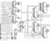
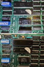
Looking at the circuit diagram more:
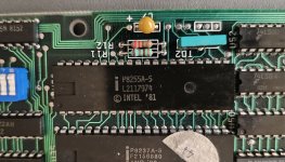
U12 and U13: Character - bits 7 to 4
U14 and U15: Character - bits 3 to 0
U8 and U9: Attribute - bits 7 to 4
U10 and U11: Attribute - bits 3 to 0
Each chip does almost half of the screen. So, if we look at the U12/U13 pair, one of those does character bits 7 to 4 for the top 1024 character positions on the screen. The other does character bits 7 to 4 for the bottom 976 character positions on the screen. 25 lines of 80 characters = 2000 characters = 1024 + 976
I would have to examine the circuit diagram more to establish which does the top and which does the bottom. Although it is probably documented somewhere.
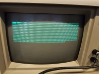
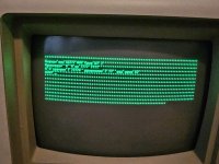
At [
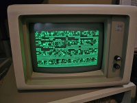
here] is the result of me tying pin 12 (connected to bit 6) of U13 to +5V. The reason why
all spaces on the screen, rather than approximately half, have changed to a ' is because pin 12 of U12 and U13 are connected, i.e. I am affecting both U12 and U13.
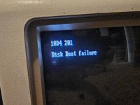
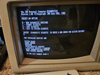
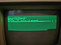
At the top-left is a bit-6-stuck-high version of "1054 201", followed underneath by a bit-6-stuck-high version of " 301", followed underneath by a bit-6-stuck-high version of "601". E.g. 31h ("1") to 71h ("q").
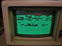
Looking back at your screenshot, I do not have an explanation for the "7777 777" (your corrupted 201 error). Why all the same character? Also, I think the ' character is different to the one that I am thinking it is.
")