• Please review our updated Terms and Rules here

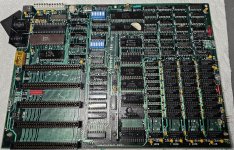
Can someone help me date my 5150?

If I was to create custom code for an EPROM/EEPROM, are you in a position to program that into a suitable EPROM/EEPROM, for IC socket U33 (in place of the BIOS ROM), together with a ROM adapter if applicable ?
For example, custom code that reads the switches and signals on/off to you via speaker beeps.
 
... but now with just the VGA card and 64KB and nothing else and set for no floppy, it doesn't boot into BASIC.
Right now I'm just hoping to see it work on just the 64KB and VGA card, ...
Yep. There is a problem right there, close to a minimal configuration.

Per [here], switches 3 and 4 in SW1 both set to OFF. Switches 1 through 5 in SW2 set to ON.

Confirm for us that initially you see a flashing cursor, then no 201 error (which if it was to occur, might flash past quite quickly), then the screen clears and 'PARITY CHECK 1' displayed. Note that once PARITY CHECK is displayed, the CPU gets halted (i.e. no possible jump into Cassette BASIC).
 
Aware of the information at [here], in particular, the comments regarding the GBS8200 ?

I would have spent a long time trying to figure out why the CGA to VGA wasn't working, thank you. I ordered an MCE2HDMI and will return the 8200, hopefully it work out of the box after setting it up with the Pi. I was going to try an MCE adapter by Necroware with the 8200, but it seems like a bunch of work for something that still isn't 100%.
I'm hoping the replacement of the tantalum caps and the cleaning and de-oxing of the sockets will yield something more stable. I will hold up on trying to adjust the PS per your post about the tolerances of the voltages and see how it goes.
I will likely be back to ask more questions after the caps come in and chips get reinstalled. Wish me luck.
Thank you for all your help. I hope to get it going again, it should get a second chance after making it this far.
 
Last edited:
If I was to create custom code for an EPROM/EEPROM, are you in a position to program that into a suitable EPROM/EEPROM, for IC socket U33 (in place of the BIOS ROM), together with a ROM adapter if applicable ?
For example, custom code that reads the switches and signals on/off to you via speaker beeps.
Sadly no, I don't have any programmers. But if I can't get it going after the cap replacements and cleaning I'll likely be buying one just to make a Rudds Diagnostic BIOS.

Per [here], switches 3 and 4 in SW1 both set to OFF. Switches 1 through 5 in SW2 set to ON.
It had always had them set off off, from what I understand the 10-27-83 bios won't let you run will anything less than 64KB.


Confirm for us that initially you see a flashing cursor, then no 201 error (which if it was to occur, might flash past quite quickly), then the screen clears and 'PARITY CHECK 1' displayed. Note that once PARITY CHECK is displayed, the CPU gets halted (i.e. no possible jump into Cassette BASIC).
I will as soon as the new caps get here.
 
Last edited:
Confirm for us that initially you see a flashing cursor, then no 201 error (which if it was to occur, might flash past quite quickly), then the screen clears and 'PARITY CHECK 1' displayed. Note that once PARITY CHECK is displayed, the CPU gets halted (i.e. no possible jump into Cassette BASIC).
Your reply may have yet to be approved of by a moderator.

PROGRESS

I brought out a known-good 16KB-64KB motherboard, one fitted with the 10/27/82 BIOS ROM. RAM sockets fully populated. SW1/SW2 set for 64 KB of RAM.

To the motherboard, I hooked up only a power supply, VGA card + monitor. Video switches on motherboard set to EGA/VGA.

Here is what I observed after flicking the power switch:
5 seconds after power applied: Cursor appeared on monitor.
9 seconds after power applied: A 301 error appeared (due to no keyboard).
10 seconds after power applied: Cassette BASIC (version C1.00) appeared.

I then removed the bit 5 chip from the second RAM bank.

Here is what I observed after flicking the power switch:
About 5 seconds after power applied, "0420 201" was displayed, with "301" under that, but only for a VERY short period of time. Then "PARITY ERROR 1" appeared.

I repeated the power-on many times. I noticed that the duration that "0420 201" and "301" was displayed varied a lot. And there were times when I did not see it at all, appearing to go straight to "PARITY ERROR 1".

And so I think that you may have a RAM chip problem. I doubt that it is in bank 0 (soldered in), because the IBM 5150 BIOS checks bank 0 quite early, and if a problem is found, simply halts the CPU (you see nothing on-screen).

This is where Ruud's Diagnostic ROM is of great benefit. It will point out bad RAM chips to you.
 
And so I think that you may have a RAM chip problem. I doubt that it is in bank 0 (soldered in), because the IBM 5150 BIOS checks bank 0 quite early, and if a problem is found, simply halts the CPU (you see nothing on-screen).

I hope so. I can easily replace those socketed RAM chips (well, after I find them), but those socketed ones would be a nightmare. Just waiting on the tantalum caps right now. I also got some solder mask for the exposed traces really close to holes where they go.

I checked all the caps on the floppy and none seem shorted, when I tested it before I had unplugged the PS from the motherboard and it was just in the floppy , perhaps it was the opposite problem, not enough load to think it should turn on.
Is it safe to test the floppy with the motherboard plugged in, will the power supply always protect itself if it sees a short that could blow something up?

Thank you for your help.
 
@MacGyverr said

Can someone help me date my 5150?​


Well, show it a lot of respect. Buy it flowers and candy. Take it out for nice dinner and maybe a concert. Do what it wants to do regardless of how silly it sounds. Listen to it without trying to fix it.

Posted on April 1, 2024 - get it?
 
Sadly no, I don't have any programmers. But if I can't get it going after the cap replacements and cleaning I'll likely be buying one just to make a Rudds Diagnostic BIOS.
They can be handy. For example, down the track, your 5150 motherboard could fail again, and someone here ask you if you are in a position to execute one of the bits of test code at [here].
 
I checked all the caps on the floppy and none seem shorted, when I tested it before I had unplugged the PS from the motherboard and it was just in the floppy , perhaps it was the opposite problem, not enough load to think it should turn on.
Maybe.

..., will the power supply always protect itself if it sees a short that could blow something up?
We hope that it was one of the goals of the power supply's engineer. It will always take time for the power supply to kick that protection in, and expected is that a competent engineer would have made sure that wires, PCB traces, etc. in the power supply would cope with the very large short-circuit current for the time-to-kick-in-period.

Of course, out of scope of the power supply's engineer, is the design of the load. For example, in the diagram at [here], capacitor C2 in the second floppy drive is short-circuit, meaning that the short-circuit current is flowing in the path highlighted in red. A possibility is that during the time-to-kick-in-period, C2 may blow itself open-circuit. If not, we hope that all conductors (wires, PCB traces, etc.) in the load's short-circuit current path will survive until the end of the time-to-kick-in-period.

I am not an electrical engineer (just a former electronics technician) and so maybe one will comment.
 
If you recommend a USB EPROM/EEPROM flasher that can work, and a chip model/adapter I can use to flash and fit into a 5150, I'll buy it.
Is this still a a good adapter? https://store.go4retro.com/2364-adapter/
I'm not trying to spend a whole bunch of money, but I'm going to need to run a low level diagnostic so I may as well get used to it.
I have no idea which model will work with what chips and under modern operating systems. (I can do USB on an old win 98 computer if i need to).
I'd just buy Rudd's from a vendor if I could find one. I've been through the vendors you listed here and they don't seem to offer it on their sites anymore, or maybe I just can't find them.
I'll try emailing this vendor and see if they can make one for me.
 
Last edited:
If you recommend a USB EPROM/EEPROM flasher that can work, and a chip model/adapter I can use to flash and fit into a 5150, I'll buy it.
Is this still a a good adapter? https://store.go4retro.com/2364-adapter/
Per [here], there are 5 options as to the EPROM/EEPROM that you can choose from.
- Some require a ROM adapter, some do not.
- If you go the EPROM route, you will need to also buy an EPROM eraser, an example shown at [here]. (Although, down the line, one might be needed for non-IBM 5150 projects.)

So, for the 5150, perhaps go the route of the Winbond W27E257 EEPROM, together with the adapter that you pointed to. And, as required, use the EPROM programmer to erase the W27E257. That combination is what I use on my 5150 motherboards.

I'd just buy Rudd's from a vendor if I could find one. I've been through the vendors you listed here and they don't seem to offer it on their sites anymore, or maybe I just can't find them.
I'll try emailing this vendor and see if they can make one for me.
The companies/people in the pointed-to list will usually provide a 'tell me what chip to supply, and what software/image you want me to put into it'. I.e. some discussion is required with them.

If you do find someone selling Ruud's Diagnostic ROM online, be aware that the version could be quite old. Ruud's Diagnostic ROM is presently at version 4.7

I have no idea which model will work with what chips and under modern operating systems. (I can do USB on an old win 98 computer if i need to).
Maybe you have read the information at [here].

My 'modernish' USB based EPROM programmer connects to a USB port on my Windows 10 machine. It is a GQ-4X, pictured at [here]. It is simply what I chose at the time (many years ago) from what models were available at the time. It suits my limited needs. More make-models are available these days. If my GQ-4X goes 'belly up', I would reevaluate the market.

If you are going the W27E257 route, then obviously, you need to ensure that the programmer supports the W27E257.

As for choice of programmer, the thread at [here] should assist you.
 
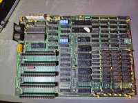
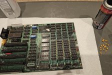
Cleaned and de-oxed the sockets, replaced all the tantalum caps. Before and after.
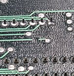
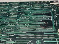
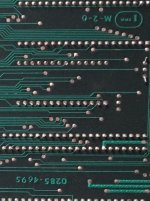
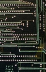
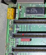
But I noticed a weird spot on the board, it looks like the trace is broken, but it looks like it was done before the solder mask was put on at the factory, is this normal?
Should I try to connect this path or was it cut like this from the factory? I circled it with the red circle on the bottom picture and included a close up.
Just waiting on the Rudd's to power it up again.
 

Attachments

  • 20240329_142354a.jpg
    20240329_142354a.jpg
    5 MB · Views: 14
  • 20240330_164815.jpg
    20240330_164815.jpg
    3.6 MB · Views: 15
  • 20240403_205741.jpg
    20240403_205741.jpg
    2.4 MB · Views: 17
  • 20240403_205945.jpg
    20240403_205945.jpg
    4.5 MB · Views: 18
  • 20240403_223620.jpg
    20240403_223620.jpg
    3 MB · Views: 14
That’s a broken trace. Here’s images from two I have.
Your second photo looks like it had that trace broken (maybe intentional modification?) too, unless I'm seeing it wrong. I only have one 16KB-64KB board and it does not seem to have this modification.
 
It does look like it came like that out of the factory though, right? I'm not crazy?
I agree (about the first question, no comment about the second question). It looks like a manufacturing defect.

In the motherboard repair thread at [here], a hole was found drilled through a trace.

Is someone selling a stockpile of tested-faulty-put-it-aside motherboards that were found at the back of a long forgotten IBM warehouse ?
 
I repaired it, I think it was pin 7 from the back on J4, which I think is IRQ4 for slot 4.
So if right I guess unless I plugged a card in set to IRQ 4, I'd likely never have noticed.
 

Attachments

  • fix.jpg
    fix.jpg
    3.4 MB · Views: 5
Back
Top