daver2
10k Member
Yep, that's where we are heading I think...
But I am trying to take the other Dave on the fault-finding journey.
Dave
But I am trying to take the other Dave on the fault-finding journey.
Dave
| VCF West | Aug 01 - 02 2025, | CHM, Mountain View, CA |
| VCF Midwest | Sep 13 - 14 2025, | Schaumburg, IL |
| VCF Montreal | Jan 24 - 25, 2026, | RMC Saint Jean, Montreal, Canada |
| VCF SoCal | Feb 14 - 15, 2026, | Hotel Fera, Orange CA |
| VCF Southwest | May 29 - 31, 2026, | Westin Dallas Fort Worth Airport |
| VCF Southeast | June, 2026 | Atlanta, GA |
G1Just been out for the evening.
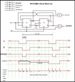
Those signals look OK.
Can you just move forwards now and check G1 pins 1, 2 and 3.
Dave
I double checked and i have same signal on the two pins.... 1,7V and some pulse.Interesting.
So, somewhere between G1/3 and G8/12 we loose our signal?
Can you double-check those two (2) pins again please.
Dave

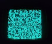
Hi Nivag,OK so I probably should have concentrated more when I blamed the monitor.
The readings above look slightly spurious...
If you consider H8 pin 13 (which should be wired directly to pin 10 also) then this is just nINIT which is simply pulled up to 5V. That should be sitting happily high.
H8 p13 needs to be nicely HIGH to get any flip flop action?
It would also be interesting to check the voltage across 7 and 14 of H8.
")
Sorry,I explained myself badly...In post #24 you state (with me reading between the lines) that you did (eventually) find a signal on G8/12.
Daver,
Ah, the dreaded state sequencer hang up. If anyone can track it down, you will. My bet is a bad 74177 counter on sheet 7, but it could be any one of a dozen ICs that went bad.
Hi Hugo, how are you?It might be worth checking that the /INIT line is staying high after booting.
So for the record please describe the signals at all pins of F2.ok so:
F2 pins 2-5-9-12 no signal (no low, no high and no pulse)
ok,So for the record please describe the signals at all pins of F2.
Dave you suggest to replace this sn177 ic?F2 has probably gone to that great TTL chip store in the sky. RIP...
Does everyone agree?
Dave
Yes!Yep - device F2, but the correct part number is SN74177.
Dave