• Please review our updated Terms and Rules here

Cbm 2001 Pet strange boot

Nice 'out of the box thinking' with the 74LS197. It does appear (at first look) to be compatible with the 74177.

>>> I changed F2 ic and now i have full screen!

It's good when a plan comes together (and still with a thread in double figures)!

So, next step - look for a SYNC pulse on pin 7 of the CPU to tell us if the CPU is executing any instructions or not.

Out with the PETTESTER...

Dave
 
Ops....

I sang victory too soon ...
I am desperate, I turned off and on the computer and now it does this defect:

 
Well, is the horizontal and vertical drive and video signal correct from the PET logic board to the monitor when the fault occurs this time?

Dave
 
Well, is the horizontal and vertical drive and video signal correct from the PET logic board to the monitor when the fault occurs this time?

Dave
Not! unfortunately i have only horizontal signal on J7 pin5 but no waves on pin3...
Now i have again horizontal line on screen and sometimes disappear also the line...
I noticed that when the line disappears, the orange light in the crt goes down a bit :(
What's can be happened? When i changed F2 ic i had full screen chars....
 
You know how to fault find the ‘horizontal line’ arising from no PET vertical drive signal now. Another IC must have gone faulty in the same part of the logic.

He he. I like the GOTO 1 :)!

The only time you should do a quick ON followed by OFF is if you let the magic smoke out of the box...

I am away on a business trip for the remainder of the week, but I will keep dipping in and out from the hotel. I will not have access to my phone during the day though.

Dave
 
If it was faulty once it could be faulty a second time I suppose - but I would have thought it unlikely (from a statistical probability).

Follow the same train of thought backwards from the vertical drive signal again.

Dave
 
Not! unfortunately i have only horizontal signal on J7 pin5 but no waves on pin3...
Now i have again horizontal line on screen and sometimes disappear also the line...
I noticed that when the line disappears, the orange light in the crt goes down a bit :(
What's can be happened? When i changed F2 ic i had full screen chars....

The 7812 voltage regulator in the VDU can just supply the full output to the VDU scan circuitry, including the CRT's heater. So if the VDU scan circuitry draws too much current, the regulator can go into a shut down mode, and the CRT heater would be seen to dim down.

An incorrect horizontal drive signal can cause this, for example if it dropped to 1/2 the usual frequency, the horizontal scan stage in the VDU would nearly double its current consumption overloading the 7812 regulator. A very high H drive pulse rate could result in that small sized raster that appeared for a while on the screen.

So likely there is something wrong with the H drive signal to the VDU and possibly still something with the vertical drive signal still too, despite the replaced IC.

I would suggest for now at least, de-power the VDU by disconnecting its connector from the VDU board end, and make sure before it is reconnected that the H and V drive signals are correct (and stable) on the scope out of the computer board, after the remaining fault/s on the computer board are fixed. This way it will be less risky for the VDU.

(Probably unrelated to your fault, but on one of the PET VDU's I had there were 360 degree ring cracks on the soldering to the pins of the connector on the VDU board which created intermittent issues there, worth checking perhaps)

PS: for the H and V drive signals to be correct they must have the correct period (or 1/frequency) and the correct duty cycle. These drive pulses and those details are drawn on on the VDU schematics on Zimmers.
 
Last edited:
I would suggest for now at least, de-power the VDU by disconnecting its connector from the VDU board end, and make sure before it is reconnected that the H and V drive signals are correct (and stable) on the scope out of the computer board, after the remaining fault/s on the computer board are fixed. This way it will be less risky for the VDU.

Hugo,
Agree! Let's protect the tube until you have good horizontal and vertical timing pulses.
 
I sang victory too soon ...
I am desperate, I turned off and on the computer and now it does this defect:
Dave78,
Don't worry, you fixed the first problem in record time. We'll all help find you find the next issue. If it turns out to be a CRT/video board issue, Hugo and the others can guide you through it. But let's make sure that the main board horizontal and vertical signals are OK.
 
Hugo,
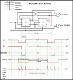
Your state sequencer timing diagram is very useful. The large gap between State 11 and State 10 is due to the circuit waiting for that 200 line signal from the counters. It marks the end of 25 rows of characters (with 8 scans per row = 200).

CBM4STATE.jpg
 
Thanks Dave_m, that helps explain some more of it.

I was thinking it would be really good to write a full functional description of the circuitry in the PET's. Because it could help greatly with diagnostics and repairs.

Of course, I noticed right away their interesting TTL logic with the outputs of counters fed back to the inputs of other IC's creating a ring configuration, as it is around IC F2. This sort of thing only works because the propagation delays of the devices and or clock timing allows it. It is like the digital equivalent of a feedback loop. And therefore it can potentially create difficulties in diagnostics & repairs. For example in an analog loop its easy enough to break it and substitute in a correct level, to find out where the failure in the rest of the loop is. With that type of digital data loop its more tricky. But, the more we know about how it works the better armed we are to fix it when it fails and make a targeted repair.

One interesting thing about the 4 state machine is, I have not figured out yet what prevents it from getting out of sequence. It must be the timing of the /INIT pulse at start up. In theory though if one of the flip flops got accidentally toggled (say while servicing with an accidental short) it could go out of step. Possibly even a burst of power supply ripple could also corrupt its sequence. So for this type of circuit it relies on a clean +5V supply, so that should be one of the first things to check. The same corruption could occur in the loop of IC's involving F2.

Interestingly on the fault with the pet on this thread, it seems to start up ok, after an episode of power cycling and corrupts later, so it would be a good idea to check the power supply. On my pet the main filter cap was defective and there was ripple on the 5V supply.

Actually the more I look at that video, the more interesting it is because, before the raster collapses due to abnormal H and V drive, the vertical scan is bouncing up and down a little. It does this if there is ripple in the V drive signal. In these PET VDU's there is a positive feedback loop in the vertical scan amplifiers, which is just below threshold for oscillations, so a slight nudge by ripple and there are a few cycles of decaying oscillation (vertical raster bounce). You can see this brief oscillation too, if you tweak the height control in these PET VDU's. I think, possibly, the power supply is corrupting the state sequencer. It would pay to scope the voltage across the 23,000uF electrolyic and check the 5V rail on the computer pcb.
 
Last edited:
Hi Hugo,
Yes, I agree about a full description as this circuit is the most hard to troubleshoot. A version of it is on all the pre-6545 CRTC PETs. The 'universal boards' of the 4000/8000 series PETs do not have all this discreet logic and counters/latches as the equivalent logic in buried in the 6545 controller chip, I assume with better synchronous logic.

Understand that this logic is complicated because it not only controls the state sequencer, but is used to address the screen refresh function that continuously reads from the video RAM to drive the character generator and subsequently the parallel to serial shift register that creates the 8 MHz video data.

The 'ring configuration' you see is needed to reload the starting address for each row of characters eight times each to complete the eight horizontal scans required for each of the 25 character rows. The starting address of each row is held in latch G3 and used to reload the counters until the eight scan lines are complete. Then the next starting row address is put into the latch. So the latch holds character address 0, 40, 80, 120, etc. which are the starting addresses of each row.

Note that the /INIT signal is only a pull-up resister (see sheet #6, lower left corner), there is no start up logic. I assume the counters would just keep counting and it would clear itself after one bad video frame of data.

Lastly, you think the current problem may have something to do with bad +5V regulation? It is worth checking out. I have not seen this type of video issue.
-dave_m
I think then , the 4 state machine must just start in the correct condition. Even though there is the long gap in the sequence of 4 pulses, it is still only a clock pulse sequence and it appears that the sequencer (each flip flop) could be in a different state for each of the bursts of groups of 4 pulses as there is nothing I could see that makes each one pulse unique. So it looks to me that it could get out of step and not be able to recover from it. But I'm not 100% sure. I would have to manually reset one of the flip flops in my PET to see if it could get it in an out of step mode.

Though I think in the case of those address counters they would just roll around.

That /INIT line appears mysterious to me that it looks like more than a pullup, as it is connected to an inverter gate input such as I1 (74S04 on sheet 6), which drives another IC (so why have that and not just tie that gate output connection low and have no gate), as well as pulling up other resets and inputs on many other IC's. Maybe there is something not shown, like a capacitor to ground on the /INIT line, that provides some form of power on reset to initialize everything including the 4 state machine, or maybe some other connection we have not found or is not documented. One other possible explanation, though I'm not sure if it washes, is that with so many device inputs connected to the /INIT line is that there is enough capacitance to reset all the devices connected to it at turn on, without having to have an actual capacitor. If the two flips flops that make up the 4 state machine were not reset to an initial condition, I think it could start up with the wrong binary state being associated with each of the 4 pulses in the group.
 
Last edited:
To the OP, having multiple faults in succession isn't at all unusual, these things are old and if they haven't failed already they contain plenty of parts that are on the verge of failing. Repair is a constant process not a one off with these beauties.

Let's have some measurements and go for the 2nd pass....

F2 and F4?
 
Back
Top