You can still perform some valuable testing with your trusty multimeter in the meantime.
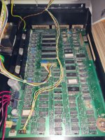
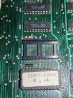
Firstly (as I now know you have a universal PET board) can you double-check the orientation of your CPU with the image below. The CPU should be UB14. Please notice the orientation of the semicircle notch in relation to the voltage regulators (e.g. VR3). I think I can see from your previous photographs that it is inserted correctly though. Always worth double checking these things though...
With the black (negative) lead of your multimeter connected to the negative (0V/GND) lead of the large external capacitor - and your multimeter set to read DC volts (5V or so full scale) measure the voltage at the following pins of the CPU (UB14). Noting that pin 1 of the IC is immediately to the LEFT of the semicircle notch as shown in the image below.
Pin 2 - RDY.
Pin 4 - /IRQ.
Pin 6 - /NMI.
Pin 7 - SYNC.
Pin 38 - SO.
Pin 40 - /RESET.
Report the voltages back please.
Dave
View attachment 1245560