• Please review our updated Terms and Rules here

Cbm 8032 capacitor

Nope, there is something still wrong with the meadurements I am afraid...

Put the BLACK lead of your multimeter on 0V/GND - and keep it there - whilst probing the two leads of each identified diode with the RED lead of your multimeter.

The 'signs' of the voltage on each pin of the same diode should be the same, with one lead having a voltage higher than the other.

Dave
 
Spot on!

So, the voltage regulators are OK.

We will continue this path tomorrow...

Dave
And by any chance would you be able to send me a writen eeprom and i could like maybe pay you by paypal for the eeprom and the transport in letter to france ?
 
Can you now double-check the reading on both leads of resistor R1 using the same measurement technique as you did for the diodes the other day. Make sure you put the black (negative) lead of your multimeter onto 0V/GND and keep it there whilst you measure the two leads of R1 with the red (positive) probe.

Dave
Did you mean the black lead of the big capacitor for the gnd ?
 
Can you now double-check the reading on both leads of resistor R1 using the same measurement technique as you did for the diodes the other day. Make sure you put the black (negative) lead of your multimeter onto 0V/GND and keep it there whilst you measure the two leads of R1 with the red (positive) probe.

Dave
And the oscilloscope i got didn't come with cables did those ones are good choice ?
 
Should there have been a link in your message somewhere?

Dave
Yes im sorry i forgot
bay.fr/itm/295017471593?mkcid=16&mkevt=1&mkrid=709-127639-2357-0&ssspo=i_kDwdIaQP2&sssrc=2349624&ssuid=gQni1uOzQj-&var=&widget_ver=artemis&media=SMS
 
Nope - I am back now. Thanks for reminding me about your thread (I had honestly forgotten).

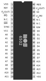
So I can't see how we can have 1V measured on both ends of resistor R1 - and 2V measured on pin 38 of the 6502 CPU (unless you are not counting the pins of the 6502 CPU properly).

Can you measure the voltage on pin 38 of the 6502 CPU again please to triple-check what the value is.

Pin 7 measuring 1V to 1.5V could (actually) be a good sign - it may indicate that the CPU is executing instructions.

How far have you got with the oscilloscope and probes new?

Dave
Sorry for not responding im not really home but i didn't ordered the probes but i will soon and i found this scheme on the internet of the processor and i was measuring the wrong side
 

Attachments

  • MOS6502.svg.png
    MOS6502.svg.png
    9.5 KB · Views: 3
Back
Top