• Please review our updated Terms and Rules here

Cbm 8032 capacitor

Your oscilloscope is actually a Tektronix 2220 - so the complete manual set (minus service manual) is here https://w140.com/tekwiki/wiki/2220.

Pin 38 (2V) is definitely not correct. This pin is an input on the CPU and is pulled up to the +5V voltage rail via a 1k resistor. The voltage should, therefore, be much higher than your reading suggests it is. We need to get to the bottom of this.

I am still confused about what is happening with pin 40 though...

If you turn the PET on (without doing anything to it) do you get any image on the screen and/or hear any sound?

If you ground pin 40 of the CPU, and then remove the link, do you then get any image on the screen and/or hear any sound?

Pin 40 is the RESET pin (and is active LOW). On start-up, this pin should remain LOW for approximately 0.5 to 1 second and then go HIGH. If pin 40 is permanently LOW, then the CPU will be held in a RESET condition and can't do anything. If, however, pin 40 immediately goes HIGH when the power is applied, the CPU will not be RESET. Grounding pin 40 will then force a RESET condition.

Dave
Now the pet is not doing anything it just happenned one time when i was measuring pin 40 and i immediately turned off thinking the sound was a capacitor on the moment but there were a patern on screen and the sound was a reapeating soud
 
Well, actually that is a good sign.

If you got a pattern on the screen, can you remember if it was random characters by any chance?

The pattern and sound indicate that the PET has powered up and started to execute code in the ROMs.

You really need to replace the EDIT ROM (UD7) with my PETTESTER ROM (available for free download - but you need to either burn your own EPROM (a single-rail 2716 or 2516 device) or ask someone nicely to do it for you). This EPROM requires the bare minimum of PET logic to operate and will then perform a test of the rest of the machine (minus some parts at the moment - but that will hopefully be rectified in the next release of the firmware).

I can point you at my Google drive repository if you can burn the EPROM.

Dave
 
Last edited:
Well, actually that is a good sign.

If you got a pattern on the screen, can you remember if it was random characters by any chance?

The pattern and sound indicate that the PET has powered up and started to execute code in the ROMs.

You really need to replace the EDIT ROM (UD7) with my PETTESTER ROM (available for free download - but you need to either burn your own EPROM or ask someone nicely to do it for you). This EPROM requires the bare minimum of PET logic to operate and will then perform a test of the rest of the machine (minus some parts at the moment - but that will hopefully be rectified in the next release of the firmware).

Dave
If i remeber the patern was like a chess plate
And the sound was clearly not the boot sound and for now the pet only does that once for now it's still not working with a black screen does a rom will really change that ?
 
>>> does a rom will really change that ?

Well, that's the challenge!

The PET clearly won't work with it's own ROMs. This could indicate a problem with the CPU, ROM, RAM, CRTC (video controller chip) or support logic. We need to identify which sub-system is at fault.

The easiest way to check to see if the CPU is working is to install a thing into the CPU socket called a NOP generator. This 'lies' to the CPU and always provides it with a NOP instruction. This should cause the CPU to burst into life and we can checkout the address lines, address buffers and address decoding using your oscilloscope.

The other way is to replace the EDIT ROM with my test ROM. This requires that the first few instructions of the Kernal ROM are intact (UD6) and then my ROM takes over the machine by programming the CRTC and displaying a known pattern on the screen. My ROM doesn't require any further ROMs to be working or any RAM. In fact, if the VDU test works OK, the next thing it does is to attempt to test the lower 512 bytes of RAM. This is the most important area of the RAM for a 6502 CPU. After that, it then displays the ROM checksums (so we can see if the ROMs are intact) and then it performs a fairly extensive test of the dynamic memory within the PET.

So, yes, replacing one ROM can tell us a lot about the health of your machine!

However, if the CRTC is dead - we won't get a picture - but (the tantalising knowledge that you did get a picture and sound at one point) does give me hope!

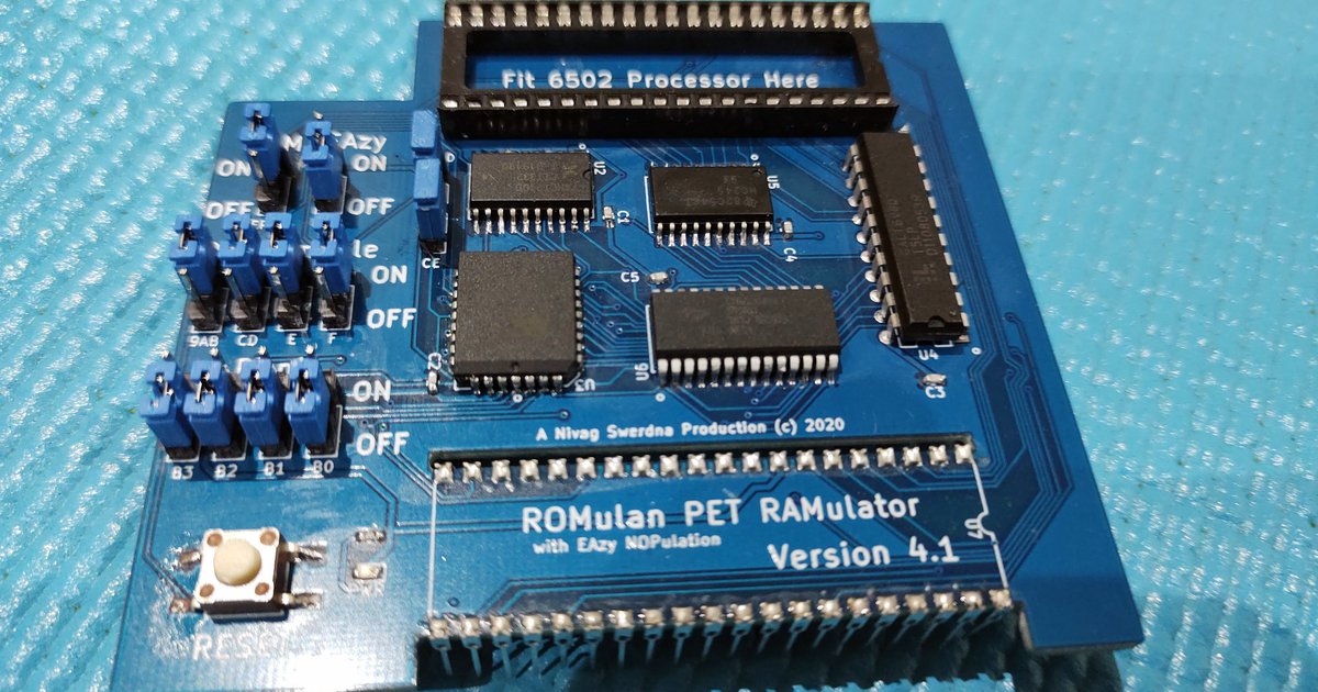
Incidentally, some of the ROM/RAM replacement boards you can get that fit into the CPU socket may also contain a NOP generator and a copy of my PETTESTER code. This is just a simple remove the CPU, insert the ROM/RAM replacement board and pop the CPU into the ROM/RAM replacement board.

We can then run my PETTESTER and (if that doesn't work) swap over to the NOP generator by just flipping a few switches. You can also replace the PET ROM/RAM with the equivalent on the board to see which (if any) of these sub-systems are causing problems - and then investigate these.

It depends on which way you would like to proceed moving forwards.

The other thing we can start doing (in the meantime) is probing around the CPU with your oscilloscope acquisition to check a few vital pins (like the clocks and SYNC pin).

Dave
What would you do at my place ?
Use a nop generator
Replace the edit rom
Or anything else ?
And could you find me the objects like on ebay or a website that can send to france ?
 
This is the point - it all depends upon what you can beg, borrow or steal!

If you can burn a 2716 EPROM (or get a friend to burn an EPROM for you) I would use my PETTESTER code first - but then I might be biased of course :)!

2716 EPROMs are still widely available. For example: https://www.cricklewoodelectronics.com/2716.html and https://www.jameco.com/z/2716-Major...nd-Electrically-Programmable-EPROM_40002.html. However, these are not in France. There will be similar electronic stores in France somewhere. But you still require to get the code into the EPROM. Alternatively, someone from VCFED might be kind enough to send you one pre-programmed in the post and you reimburse them for their costs + a beer or two...

A NOP generator can be made yourself from a couple of 40 pin sockets and some resistors (if you are able to follow a very simple schematic and solder).

If the above are beyond your current skillset, then ROM/RAM replacements can be purchased:

https://bitfixer.com/product/romulator/ (but as a kit). Ask and you may be able to purchase a ready built unit?


Or we can just look at some signals with the oscilloscope in the meantime. There is no right or wrong path.

Dave
Can this be able to burn an eprom and what software can i use ?
can you make me a tutorial ?
 
This is the point - it all depends upon what you can beg, borrow or steal!

If you can burn a 2716 EPROM (or get a friend to burn an EPROM for you) I would use my PETTESTER code first - but then I might be biased of course :)!

2716 EPROMs are still widely available. For example: https://www.cricklewoodelectronics.com/2716.html and https://www.jameco.com/z/2716-Major...nd-Electrically-Programmable-EPROM_40002.html. However, these are not in France. There will be similar electronic stores in France somewhere. But you still require to get the code into the EPROM. Alternatively, someone from VCFED might be kind enough to send you one pre-programmed in the post and you reimburse them for their costs + a beer or two...

A NOP generator can be made yourself from a couple of 40 pin sockets and some resistors (if you are able to follow a very simple schematic and solder).

If the above are beyond your current skillset, then ROM/RAM replacements can be purchased:

https://bitfixer.com/product/romulator/ (but as a kit). Ask and you may be able to purchase a ready built unit?


Or we can just look at some signals with the oscilloscope in the meantime. There is no right or wrong path.

Dave
And also what does the voltage on pin 38 indicate you said it was not correct i dont think the rom have to do something with it ?
Yes ?
 
I don't think the linked device will work for 2716 eproms. From my experience with trying to burn a pettest ROM you should look for a programmer which supports your eprom type but also its required programming voltage (21V/25V, check the data sheet).
Usually you won't find new programmers which can do this (except maybe the GQ-4x). If you're not planning to program several ROMs for different computers it might be easier to just get a preprogrammed pettest ROM
 
And also what does the voltage on pin 38 indicate you said it was not correct i dont think the rom have to do something with it ?
Yes ?

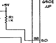
As you can see below, pin 38 is just a resistor pulling up an INPUT pin to +5V. Pin 38 is an INPUT to the 6502 microprocessor. If this voltage is incorrect, it indicates one of a few potential scenarios:

1. One of the +5V regulators is not supplying the +5V rail to this resistor. Locate R1 and measure the voltage on both ends of the part and report the readings.

2. The resistor is damaged.

3. The PCB tracking is damaged.

4. A measurement error by the operator...

You are 100% correct in that the ROM doesn't have anything to do with this. I generally include pins 2 and 38 into the initial readings to act as a 'check' that readings are being taken correctly and there is nothing 'strange' going on. I like to get to the bottom of things that do not turn out to be correct...

Dave

1662135472316.png
 
As you can see below, pin 38 is just a resistor pulling up an INPUT pin to +5V. Pin 38 is an INPUT to the 6502 microprocessor. If this voltage is incorrect, it indicates one of a few potential scenarios:

1. One of the +5V regulators is not supplying the +5V rail to this resistor. Locate R1 and measure the voltage on both ends of the part and report the readings.

2. The resistor is damaged.

3. The PCB tracking is damaged.

4. A measurement error by the operator...

You are 100% correct in that the ROM doesn't have anything to do with this. I generally include pins 2 and 38 into the initial readings to act as a 'check' that readings are being taken correctly and there is nothing 'strange' going on. I like to get to the bottom of things that do not turn out to be correct...

Dave

View attachment 1245619
I got 0v on r1
 
Now that IS interesting...

Can you measure and report back the voltages on both ends of the following diodes again please:

CR1
CR5
CR6
CR7

Dave
 
Sorry, we have a misunderstanding somewhere. My fault.

Can you measure the voltage on BOTH leads of each diode please (8 voltage readings in total)?

Cheers,

Dave
 
Back
Top