• Please review our updated Terms and Rules here

Cbm dual drive 3040 disk - two red lights

Let's not bother about drive 1 for now then.

After you have formatted drive 0 what happens if you then do a LOAD "$",8? If you get READY back try LIST.

Also don't forget to enter PRINT ST after the format command and see if you got any error back.

Dave
 
After you have formatted drive 0 what happens if you then do a LOAD "$",8? If you get READY back try LIST.
I don't think the disk is formatted ... the head stays still and then the red central led appears .. i am desperate
 
Well, the stepper and motor control signals originate from 6522 UM3. Is this the device that was inserted the wrong way round?

If so, I would suggest replacing it with a new device before we continue - as we don't know what damage has occurred do we?

Dave
 
Well, the stepper and motor control signals originate from 6522 UM3. Is this the device that was inserted the wrong way round?

If so, I would suggest replacing it with a new device before we continue - as we don't know what damage has occurred do we?

Dave
Yes...ok i look if i have a new one!
Thanks!
 
Well, the stepper and motor control signals originate from 6522 UM3. Is this the device that was inserted the wrong way round?

If so, I would suggest replacing it with a new device before we continue - as we don't know what damage has occurred do we?

Dave
I changed UM3 but i have same problem :(
 
You need to download the test code for the 2040/3040 and run that I am afraid.

I had found an online copy this afternoon - but I have forgotten where now!

Dave
 
You need to download the test code for the 2040/3040 and run that I am afraid.

I had found an online copy this afternoon - but I have forgotten where now!

Dave
Ok Dave but how can i do to transfer this program from Mac Osx to cassette?
Thanks so much
 
Ok Dave but how can i do to transfer this program from Mac Osx to cassette?
Thanks so much
This is another case where the SD2PET would help you, as its easy to get the program onto the SD card in a modern computer. Also, if you got one it would help confirm that your IEEE-488 port is in perfect order.
 
>>> Ok Dave but how can i do to transfer this program from Mac Osx to cassette?

No idea I am afraid. Perhaps someone else can help with this question.

So, to summarise where we are, we appeared to have a 6502 CPU that didn't work - but then decided to work for no apparent reason; a faulty 6530 (UK3) - replaced by an adapter board; and a 6522 (UM3?) that was installed the wrong way round. Does this coincide with your recollection?

I think there is a high probability now that the IEEE488 port is working - as the drive does something when you command it to from the PET. That is good news.

I am now thinking of some ways to test out the digital logic board to analogue board to disk drive interfaces.

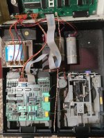
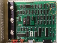
Can you post EXACTLY what digital board you have (there appears to be two variants - Rev G and H) and what analogue board you have (there may be a couple of versions of this also). Also, what make and manufacture of physical disk drives you have.

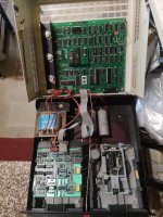
You should have a digital board in the top of the case connected to the left-hand-side disk drive containing an analogue board and the right-hand-side disk drive should be a 'bare' drive with very little (if any) electronics on it.

Can you also note which plugs and sockets are connected to where. It is easy to get the plugs and sockets accidentally reversed with two drives (I have done it myself - but on a DEC machine not a Commodore). I plugged the head cable into the drive 0 connector and the digital cable into the drive 1 connector. It was never going to work that way round - and it didn't!

You can see an open drive here: https://www.vintagecomputer.net/commodore/2040/CBM_2040_lid-up.jpg.

EDIT: I have some new tests now I have worked out how the logic board, the analogue board and the disk drives are interconnected. Later on...

Dave
 
Last edited:
For users who have a real disk drive and also want to add an 'electronic' clone the SD2PET is not necessarily the best choice because it has no IEEE port through connection to allow the connection of both the SD2PET and the 'real' disk drive. You would almost certainly want to be able to connect both at some point and give then different drive IDs so you can transfer programs from one to the other.

In this respect it appears that the PETDiskMax has better native support for multiple chained devices, so that might be the better option for anyone who already has a real FDD drive unit to go for. The SD2PET is really designed to be an alternative to / substitute for a real FDD unit.

However, both of these items are quite expensive and Desperado already has a real dual FDD drive.

ScottishColin pointed out that there was an interesting Raspberry PI project which can serve as a substitute Commodore cassette unit - I don't know much about it but I assume you can load files onto the Raspberry Pi which then communicates with the PET using the same data signalling method as an actual Commodore cassette unit, such that the PET does not actually know the difference.


I'm sure there will also be an equivalent Arduino project as well, does anybody know? If Desperado already has access to either of these micro tools then it might be worth trying to use one of these to get the Disk tester program into the PET.
 
The Pi/PET cassette drive page and code is here:


I have some spare PCBs already made up (I had to order a minimum of 5) if anyone wants one.

Colin.
 
As RPis are rather expensive these days (remember when they were 20-30 bucks), there's the Tapuino / TapuinoNext projects as an alternative
 
'Big' Raspberry Pis are not insignificantly priced now (although Desperado may already have one) but the project referred to in #652, #653 can be run on a Pi Zero, which is still quite reasonably priced. I'm not suggesting that Arduino based solutions aren't equally valid.

Judging by Daver2's last edit he still isn't out of ideas, so we had better jump clear again for now.
 
Last edited:
So, to summarise where we are, we appeared to have a 6502 CPU that didn't work - but then decided to work for no apparent reason; a faulty 6530 (UK3) - replaced by an adapter board; and a 6522 (UM3?) that was installed the wrong way round. Does this coincide with your recollection?
Yes Dave!
 
Excellent.

Can you post an overall view of the cards and cables within your disk drive please.

The connectors identified as P8 and P10 on the smaller analogue board should go to the bare disk drive on the right hand side of the unit (drive 0).

Can you also measure the DC voltage (using your multimeter) on R7, R8, R11 and R12 (all 680 Ohms). You will note that one end of resistors R7 and R8 are connected together. This is the point to measure. Likewise for R11 and R12. This will indicate whether you have both +12VA and +12VB available on the analogue board. These measurements are to be taken with the black/negative multimeter lead on 0V/GND.

Have you still got the manual reset pushbuttons we installed on both the PET computer and the disk drive fitted? Just thinking ahead...

Dave
 
Ok so:
 

Attachments

  • 1664207290607..jpg
    1664207290607..jpg
    2 MB · Views: 9
  • 1664207323266..jpg
    1664207323266..jpg
    3.2 MB · Views: 9
  • 1664207344559..jpg
    1664207344559..jpg
    1.8 MB · Views: 9
Can you also measure the DC voltage (using your multimeter) on R7, R8, R11 and R12 (all 680 Ohms). You will note that one end of resistors R7 and R8 are connected together. This is the point to measure. Likewise for R11 and R12. This will indicate whether you have both +12VA and +12VB available on the analogue board. These measurements are to be taken with the black/negative multimeter lead on 0V/GND.
ok 12,2 V for each resistor!
Have you still got the manual reset pushbuttons we installed on both the PET computer and the disk drive fitted? Just thinking ahead...
yes but only in disk drive :(
 
Back
Top