• Please review our updated Terms and Rules here

Cbm dual drive 3040 disk - two red lights

I have now finished my "work" (I am going away on a business trip tomorrow for a few days - but I wanted to get some stuff cleared off my plate over the weekend). It does mean I can spend a bit of time when I return playing with my own vintage computers though...

Let me do the washing up first, and then I will get back to posting...

Dave
 
OK, I am back...

First thing. We are going to apply a shorting link onto the right-hand disk drive (drive 0) motor speed controller PCB.

This process can (if we get it wrong) short out the +5V supply to 0V/GND - and we don't want that do we?!

We do NOT apply any power to the disk drive until we are convinced we have got the link in the correct place.

With the POWER OFF, can you use your multimeter to measure the RESISTANCE between pins 7 and 14 of UB2 (74LS04) on the analogue board please. Pin 7 = black lead (0V/GND) and pin 14 = red lead (+5V). This reading will give us a baseline result to test for later (before applying power) to ensure that we haven't inadvertently shorted out the +5V rail!

Please post the resistance reading back when you have taken it

Dave
 
I am not going to tell you until you have posted back the resistance reading I have asked for.

We will take this a step at a time to prevent getting it wrong if you don't mind.

I will provide a photograph of where the link should go for you.

Dave
 
I am not going to tell you until you have posted back the resistance reading I have asked for.

We will take this a step at a time to prevent getting it wrong if you don't mind.

I will provide a photograph of where the link should go for you.

Dave
115 Ohm
 
Excellent.

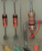
So, on the right-hand side disk drive motor speed controller board you should see (by the cables) the following components:

1664721972162.png

Apply a temporary link from the end of the 2k resistor to the nearby 0V/GND track as marked in RED.

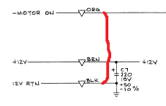
This should, if I am correct, connect the orange motor control input wire to 0V/GND. As this signal is active LOW - when we apply power (BUT NOT JUST YET) this should cause the motor to run on the right-hand side disk drive.

What we are doing (from a schematic point of view) is this:

1664722165914.png
Let me know if (A) this is confusing or (B) when you have done this.

We will then perform some tests to make sure the link is in the correct place...

Dave
 
Excellent.

So, on the right-hand side disk drive motor speed controller board you should see (by the cables) the following components:

View attachment 1246872

Apply a temporary link from the end of the 2k resistor to the nearby 0V/GND track as marked in RED.

This should, if I am correct, connect the orange motor control input wire to 0V/GND. As this signal is active LOW - when we apply power (BUT NOT JUST YET) this should cause the motor to run on the right-hand side disk drive.

What we are doing (from a schematic point of view) is this:

View attachment 1246873
Let me know if (A) this is confusing or (B) when you have done this.

We will then perform some tests to make sure the link is in the correct place...

Dave
Ok wire solded!
 
We will do two (2) tests.

I will post the first one now - and the next one in the next post.

Can you repeat the following resistance test please:

With the POWER OFF, can you use your multimeter to measure the RESISTANCE between pins 7 and 14 of UB2 (74LS04) on the analogue board. Pin 7 = black lead (0V/GND) and pin 14 = red lead (+5V).

The reading should be approximately 115 Ohms again (thus indicating we haven't short circuited the +5V rail to 0V/GND).

Dave
yes again 115 Ohm !
 
Excellent. So we haven't screwed up there...

The next test is to remove the right-hand side black disk drive connector from the analogue board.

Follow the ORANGE and BLACK leads back from the motor speed controller PCB to the black disk drive connector and then measure the resistance between the two pins that these wires are connected to. I think they are pin 14 and 'K'. This resistance reading should read 0 Ohms (a short circuit) assuming we have placed our link in the right place on the motor speed control board.

If this is OK, reconnect the black disk drive connector to the analogue board.

I have just thought of a further test before we power up - but I will post that one in my next post to save doing too many things in one go.

Dave
YES, 0 OHM!
 
Excellent.

Reattach the black disk drive connector back onto the analogue board (if you haven't already).

Locate the 1k resistor R4 on the analogue board. This should be close to the black disk drive connector.

Use your multimeter to measure from both sides of the resistor leads back to pins 7 and 14 of IC UB2 (74LS04) on the analogue board.

One side of resistor R4 should be 0 Ohms (a short circuit) to pin 14 of UB2.

The other side of resistor R4 should be 0 Ohms (a short circuit) to pin 7 of UB2.

Otherwise, the resistance reading will be approximately 115 Ohms again.

Report back your findings.

Dave
 
Excellent.

Reattach the black disk drive connector back onto the analogue board (if you haven't already).

Locate the 1k resistor R4 on the analogue board. This should be close to the black disk drive connector.

Use your multimeter to measure from both sides of the resistor leads back to pins 7 and 14 of IC UB2 (74LS04) on the analogue board.

One side of resistor R4 should be 0 Ohms (a short circuit) to pin 14 of UB2.

The other side of resistor R4 should be 0 Ohms (a short circuit) to pin 7 of UB2.

Otherwise, the resistance reading will be approximately 115 Ohms again.

Report back your findings.

Dave:(
I don't understand sorry... need i measure resistance on R4 or from R4 to Ub2?? :(
Can i turn on please?
 
Ok, lets take it slower...

Put one lead of your multimeter (say the black lead) on to UB2 pin 7.

Then use the other lead of your multimeter (the red one) to measure the resistance reading to first one lead of resistor R4 and then the other lead of R4. One of them should indicate 0 Ohms.

Then, move your black multimeter lead from UB2 pin 7 to UB2 pin 14.

Then use the other lead of your multimeter (the red one) to measure the resistance reading to first one lead of resistor R4 and then the other lead of R4. One of them should also indicate 0 Ohms.

Is that more clear?

Dave
Ok thanks, then I had already tried .... correct ... o Ohm!
 
OK,

Power on :)!

The right-hand side disk drive motor (drive 0) should start to rotate as soon as you turn the power on. If this is the case, turn the power off and report back.

This SHOULD work - as I believe you had drive 0 running previously. I am using this as the 'test case' for the drive that didn't rotate (in the next set of tests with that drive)...

Dave
 
The right-hand side disk drive motor (drive 0) should start to rotate as soon as you turn the power on. If this is the case, turn the power off and report back.
Yes, the right motor is now spinning!
 
Excellent!

OK - remove the temporary link that you added to the motor speed controller PCB and retest (with the power ON to make sure the motor DOES NOT automatically start when you power on this time).

Report back when you have done this.

Dave
 
Excellent!

OK - remove the temporary link that you added to the motor speed controller PCB and retest (with the power ON to make sure the motor DOES NOT automatically start when you power on this time).

Report back when you have done this.

Dave
Ok, right drive doesn't spin now!
 
Back
Top