daver2
10k Member
Sounds fine as well.
Dave
Dave
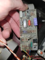
Measure the resistance between the following points of the disk drive connector and report the values back. We are looking for a similar resistance for each winding. Repeat the test for both disk drives.
Pin 12 (RED) and pin M (BROWN) - Phase C.
Pin 12 (RED) and pin P (BLACK) - Phase A.
Pin 11 (RED) and pin N (ORANGE) - Phase D.
Pin 11 (REd0 and pin R (YELLOW) - Phase B.
Also measure the resistance between pins 11 (RED) and 12 (RED). This reading should be a high resistance (as opposed to the others).
0 ohm for both drives.Also measure the resistance between pins 11 (RED) and 12 (RED). This reading should be a high resistance (as opposed to the others).
Yes disconnected! On multimeter i read 0....reading stands still ...You do have the black disk drive connectors disconnected from the analogue board don't you?

No problem - only do work when you are not tired (otherwise you will make mistakes).I hope not to offend you, but I will continue the tests tomorrow ... tonight I am very tired, I was late for work
Drive 0 : 43,9 ohmThe best place may be 0V/GND and the negative end of C6 (follow the PCB tracking back from the RED lead of the motor):
.With probes shorted together i read 00,0 Ohm, without shorted i read 0.L MohmSo, your motors don't look faulty. This implies that your non-working drive motor is either down to human error or the speed controller electronics (i.e. it is fixable). We just have to identify what is faulty - but we can work on that presently.
Can we go back to the stepper motor readings again please now you are a bit less tired
In particular post #702 (where we have the 0 Ohm reading) and #703 (where both readings are 0 Ohms).
Out of interest, what does your multimeter indicate when set to the same configuration as you have been using for testing with the probes open circuit and shorted together?
Dave
I am desperate!! Both drivers s' connectors haven't continuity between pins 11 and 12... i read 0 ohmOK.
So, can you check between pin 11 (RED) and pin 12 (RED) of the disk connectors again (both of them) and tell me what you get again.
If you get 0 Ohms again (a short circuit) can you check the connector and surrounding pins and wiring for obvious signs of short circuits [i.e. the gold fingers of the connector shorting to somewhere they shouldn't or loose strands of wire shorting out on the rear of the connector (where the wires attach to the pins of the contacts)].
These two pins (11 and 12) should NOT be connected together. They are the two centre taps of the four stepper motor windings. There should be two (2) phases of the stepper motor connected to each centre tap.
Dave
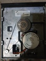
This is step by step motor with wires.Yes, that's a Shugart 390 disk drive (a cut-down SA400). I think it is the same type that is used in the Apple II.
I have found various stepper motors on ebay with the same part number - but (strangely) they appear to have slightly different wire colours.
Exactly what colours are your wires going to the stepper motor?
One of the stepper motors I have found is actually marked with the resistance of each phase winding - 36 Ohms.
This looks consistent with your readings in post #702 with the exception of one reading. Can you remeasure DRIVE #1 pin 11 (RED) to pin N (orange) and report back what you read.
It is very unusual to have a stepper motor winding that shorts out. I would expect a winding to go open circuit.
The same for the two RED centre tap wires - to have both stepper motors go faulty in exactly the same way would be extremely improbable.
Dave