Desperado
Veteran Member
- Joined
- Nov 25, 2017
- Messages
- 6,827
36 OHMCan you remeasure DRIVE #1 pin 11 (RED) to pin N (orange) and report back what you read
36 OHMCan you remeasure DRIVE #1 pin 11 (RED) to pin N (orange) and report back what you read
pin 12 and 12..... 0.L M Ohm for both drivesExcellent, that's the beast..
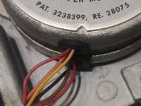
You can see quite clearly two (2) bundles of wires:
1. RED, ORANGE and YELLOW.
2. RED, BLACK and BROWN.
The first bundle (RED, ORANGE and YELLOW) contains phases B and D.
The second bundle (RED, BLACK and BROWN) contains phases A and C.
The two (2) red wires (one from each bundle) should go to the black drive connector pins 11 and 12.
The RED wire from the RED, ORANGE and BROWN bundle should go to pin 11 of the black drive connector.
The RED wire from the RED, BLACK and BROWN bundle should go to pin 12 of the black drive connector.
With the black drive connector disconnected from the analogue logic board, can you measure the resistance between the two (2) RED wires that you follow back from the two bundles of wire from the stepper motor to the black drive connector please.
Dave
yes sorry 11 to 12!>>> pin 12 and 12..... 0.L M Ohm for both drives
I assume you mean pin 11 and pin 12?
So, I assume that reading is open circuit? (which it should be)
Dave
Oh! Tuo figlio è un ragazzo fantastico!Mi dispiace che la mia seconda lingua non sia l'italiano. Durante il lockdown mio figlio stava imparando l'olandese. Ora sta imparando anche il norvegese!
High signal for each pin....i take 5v for supplying logic probe...correct?Using your logic probe - the HIGH/LOW/PULSE status of pins 1, 5, 9 and 13 on UC1 (74LS04).
CR1: 0,6 - 0,6 VCR1 through CR16 (16 diodes and 32 voltage readings).
") Thanks!
Thanks!