• Please review our updated Terms and Rules here

CBM PET 3032 STRANGE BOOT

Ok, put your probe back to x1 (and readjust your oscilloscope Y scale again).

Let's note this strange measurement and move on. CLK8 (the 8 MHz clock) should be there for the display to be working. But I am surprised that your oscilloscope is loading that pin up like that.

Let's move on to E11 pin 1.

Dave
 
Ok this is E11 pin 1
 

Attachments

  • 1679142361308..jpg
    1679142361308..jpg
    1.1 MB · Views: 4
  • 1679142387005..jpg
    1679142387005..jpg
    1.2 MB · Views: 4
In a TTL circuit, if attaching a scope to an output pin alters anything, especially with a x10 probe that has an input capacitance of around 30pF and 10 Meg ohms, it strongly suggests that the output pin (output stage in the IC) has lost the ability to sink current and/or source it as it should. In other words I would be very suspicious of a TTL chip where this happens. I have had an occasional case where it did and the chip was defective. TTL chips sink current better than they source it, but still, at all times, should be able to drive the input impedance of a scope probe. I will have to look at the schematic to see if there is any other reason why the scope probe might affect that part of the circuit.
 
Excellent work.

@Hugo Holden, my thoughts exactly... I don't want @Desperado to warm up the soldering iron just yet though...

We will now slow down and look at one signal at a time using your oscilloscope. The signals are now going to get more complex. Unfortunately, we have done all of the 'simple' signals...

Now we are going to have a look at H11 pin 1.

This signal should give us a pulse at the end of each video line. There should be a regular series of pulses whilst drawing the raster on the video screen, and then a 'gap' whilst the video beam is moving from the end of the screen to the beginning.

Start off with the timebase fast and slow it down until you see a few cycles of the high frequency pulses. Take a shot of the oscilloscope screen along with the timebase setting.

Set the timebase to 5 ms/div and take another shot of the oscilloscope screen.

Dave
 
....possibly either IC G5 is defective, but another cause could be a high resistance socket or track connection between G5 CLK8 signal and E11 pin2. The simple way to tell if it might be the IC or the interconnect is to touch the scope on pin 3 of G5 and see if the same thing happens, or not.
 
Ok this is H11 pin1
 

Attachments

  • 1679145399878..jpg
    1679145399878..jpg
    1.1 MB · Views: 4
  • 1679145418237..jpg
    1679145418237..jpg
    1.2 MB · Views: 4
I am afraid that photograph doesn't help me. The timebase is too slow for the photograph.

Can you see a 'gap' in the waveform with your eyes? If not, speed up the timebase 1 click clockwise...

Dave
 
I am afraid that photograph doesn't help me. The timebase is too slow for the photograph.

Can you see a 'gap' in the waveform with your eyes? If not, speed up the timebase 1 click clockwise...

Dave
I can start see a waveform only with thi setting
 

Attachments

  • 1679145956634..jpg
    1679145956634..jpg
    1.1 MB · Views: 4
  • 1679145976172..jpg
    1679145976172..jpg
    1.2 MB · Views: 4
That's OK. The 'gap' may not be too noticeable. That signal is probably fine also.

Ok, the signal I am really interested in now! H11 pin 2. This signal (NEXT) should be a narrow high-going pulse. When this signal goes HIGH it will reset the counter H11.

Adjust the timebase so that you can see some cyclic waves on the screen, and look at the HIGH level of the signal to see if it is varying in time (getting longer and shorter).

Do you have any spare 74191 devices? I assume G5 is currently soldered in (as opposed to being in a socket)?

Dave
 
Sorry, you are not looking hard enough!

There SHOULD be a signal here, and it should be a very narrow pulse. You have to adjust the timebase, trace brightness etc. to observe it...

Dave
 
To see something, i setting voltage knob to 0.1V and time div to 0.2 us... After some minutes, screen is full of horizontal lines and the E disappears
 

Attachments

  • 1679149267523..jpg
    1679149267523..jpg
    1.2 MB · Views: 6
  • 1679149290357..jpg
    1679149290357..jpg
    1.1 MB · Views: 4
  • 1679149300987..jpg
    1679149300987..jpg
    1.2 MB · Views: 5
  • 1679149313163..jpg
    1679149313163..jpg
    1.3 MB · Views: 6
Things seem to change too fast for me on this thread so I am now lost. Do we have a new fault? We know that at least half of H11 is fine... it is required to render the characters.

Can I have a summary of the state of play please?

If we are starting to doubt CLK8 at pin 3 of G5.... can we get a nice trace when the machine is just started? Does it disappear after a while?
 
Last edited:
That is not a wave you are seeing, that is noise.

Can you just recheck pin 1 of H11 and look at pins 8, 9 and 11 of H11.

Nivag, I will reply to your question in a few minutes.

Dave
 
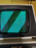
Nivag, we started chasing why we are not getting a full screen of 'E' characters.

My guess is that the character row counter (H11) was misbehaving (either internally or as a result of the signals being fed to it).

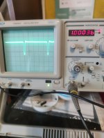
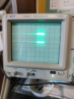
I came to this conclusion by frame stepping the video that @Desperado posted and I could see the bulk of the screen (75 to 80% or so) had an 'E' character, with the remaining screen characters having (what appeared to me) to be the wrong part of the 'E' character displayed.

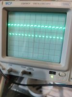
We looked at the data input and output of F9 and those seemed as solid as a rock. Basically, at the static levels of the PETSCII for the character 'E'.

I then set 
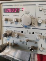
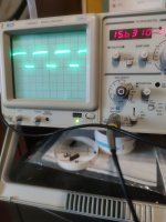
@Desperado the task of just looking at some of the simple logic signals around this schematic to (a) get him used to using his oscilloscope again and (b) looking for anything untoward.

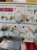
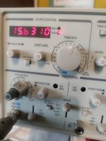
In probing around, we found that measuring E11 pin 2 (CLK8) had a disastrous affect on the circuitry. This has led both Hugo and myself to suspect G5 is not driving too well, or when G5 was replaced, the soldering, PCB tracking or whatever is not too good.

Now what seems to have happened is that what WAS a temperature-related issue is now a permanent issue? So, we need to identify why...

G5 being partially faulty could account for a number of observed issues with this machine. However, @Desperado doesn't have any more spares of this device.

I hope that catches you up with today's work?

Dave
 
Back
Top