• Please review our updated Terms and Rules here

CBM PET 3032 STRANGE BOOT

As you have reported that with the VIA in socket you have no continuity from the leg of pin 29 of the VIA to pin 19 of the char gen then that will leave the line floating.

Once the VIA output CB2 is connected to pin 19 of the char gen then it will be able to drive the line positively high or low.

So check pin 29 of the VIA and make sure its clean, maybe try to clean the socket and if you cant get continuity between the pin and the track then its time to change. You did say you could get continuity between the socket and the char gen so I'm assuming the tracks are ok and that maybe the socket has splayed and not gripping the pin.
Gary are you sure that pin 29 of C5 must be connected with pin 19 of chars rom? I removed Via socket and i cleaned the board but i have not continuity across these pins....i have continuity across pin chars rom pin 19 and VIA pin 39!
 
Lets start again

C5 is the VIA and pin 39 is the one we are interested in

1679683154456.png

That pin (labelled GRAPHIC) goes to pin 19 of the character gen address line 10 to select different character sets.

You need to check with the VIA and the Char ROM in place between C5 leg 39 and Char ROM leg 19

1679683083318.png

Hope thats clear and apologies for errors :)
 

Attachments

  • 1679682940031.png
    1679682940031.png
    257.2 KB · Views: 1
You need to check with the VIA and the Char ROM in place between C5 leg 39 and Char ROM leg 19
Gary but I already told you yesterday (post 726) that I had continuity between these two pins... I had no continuity with pin 29...
 
The actual, physical leg of the VIA pin 39 to the actual physical leg of the Char ROM pin 19 ?

IF you have continuity between these points and the line is glitching then the VIA isn't pulling down the line properly. Now this could be the VIA, or there is a bad connection.

The fact that a probe on the pin 19 of the char rom gets rid of the glitches shows that it is this line thats spiking and the probe is either physically affecting it and its forcing the ROM to make contact, or the probe is allowing the noise to pass away.

So, use a length of wire, put one on pin 39 of the via and one on pin 19 of the Char ROM. Do the glitches stop ? (be careful)
 
The actual, physical leg of the VIA pin 39 to the actual physical leg of the Char ROM pin 19 ?
Yes, noi i soldered new socket, i inserted the VIA and i turn on the computer....i am waiting if something happens..
 
Now we are at pettester Dram 8 pass and i haven't see yet noise or glitches on screen!
 
As I understand it, Desperado had been running the computer without the VIA (or PIA's) inserted in their sockets, see post #722, and this is why the line to the character ROM was floating and picking up noise causing it to strobe between upper and lower case.

But I'm not sure if that connection was also coincidentally broken & floating due to a damaged socket when the VIA was put back in as well. That would have been an interesting coincidence.

Now this noise issue is resolved, the question is; is there a remaining fault to be found ? the one that appeared to stop the computer and possibly be thermally related.
 
Yes Hugo, now need i understand if pet works fine....time to remove nivag's board?
 
Yes Hugo, now need i understand if pet works fine....time to remove nivag's board?
I guess at this point you could return the PET board to standard for testing and running a few programs. If it fails though, you would need to put Nivag's board back in and start from scratch with the testing.
 
index.php

Move the top left jumper under the word RAM from middle to top to middle to bottom, ie from ON to OFF
 
Did the screen glitches only ever occur with the VIA out ? might not have actually been a real problem, just that with the VIA out, the line between the VIA and the Char gen was susceptible to noise.

Anyway, if its gone with the VIA in, its probably not coming back. To check the line works properly type POKE 59468,12 and back type POKE 59468,14 and you should see pin 39 of the VIA going high and low which changes the address A10 of the char ROM and the characters on the screen should change upper and lower case.
 
I am desperate.... With Ram button switched to Off, pettester stuck on this screen
 

Attachments

  • 1679741297414..jpg
    1679741297414..jpg
    3.9 MB · Views: 2
So, to confirm, are we happy that the video circuitry is not producing 'glitches' anymore when things warm up?

So the DRAM in the PET (or the supporting circuitry) is probably faulty.

If things 'get stuck', as this has, what is the first thing we always test for?

Dave
 
I cannot think of how to figure out what is going on here, partly because I don't understand the ins & outs of Nivag's tester or the memory test protocol used.

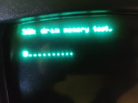
What I would do, if it was my computer, is put it back into a standard condition and attempt to initially run some simple programs and see if BASIC was "basically working" or not. Generally, if it is, the lower 2k of DRAM memory will probably be ok.

If BASIC was not operational, or the computer was locking up, I would suspect the DRAM IC's. In my case, with my DRAM diagnostic system, I would use it where added SRAM substitutes in for the lower 2k DRAM, to ensure BASIC works reliably, and then I run the diagnostic programs (in an added ROM) to check the 4116 DRAM IC's, for the purpose identifying the faulty DRAM chips. And I would check with the scope that the DRAM IC support circuitry is normal compared to the 21 or so scope recordings I made. The DRAM IC's can actually be ok, but malfunction if there is a fault in their support/refresh circuitry:


I explained every step about it, in the article and how to find faulty DRAM IC's.

But, you don't need my system at all, if you have Nivag's board or Daver2's PET tester, which are more sophisticated at both the hardware and software level than my test system, but you will have to know how to operate these systems correctly, and read the manuals thoroughly, and interpret the results correctly, or it might make no sense to you.

I'm sure Nivag will help guide you through how to use his board find where the problem is located.
 
Hugo,

To answer your questions.

1. Nivag's board just maps ROM and/or RAM either external (using the PETs) or internal. There is a data bus buffer involved (or similar) so the PETs data bus is isolated from the internal bus. The (previously working) test was with internal ROM and RAM. Flipping the RAM link over causes PET RAM to be used instead of internal.

2. The PETTESTERs DRAM test is a slightly modified MARCH-C memory test. By slightly modified I have added two tests. One to clear memory to all $00 and validate this. The other to preset memory to all $FF and to validate this. Technically, these tests are performed by the MARCH-C tests anyhow. The MARCH-C memory tests are a recognised high coverage test for dynamic RAM devices. The only thing that I am planning to add to these tests in Version 5 is an inherent 'delay' between the $00 and $FF writing and validating steps to ensure the DRAM refresh circuitry is performing it's job.

However, there is a slight 'niggle' with my MARCH-C test. It uses both page 0 RAM and the stack (page 1 RAM) and relies on this working... I have a (too simple) memory test for pages 0 and 1 of the RAM before I use them in anger. I have found that some marginal RAM failures can pass the simple tests but cause the full memory test to crash (or malfunction). This malfunctioning has already been observed on Desperado's PET (it was reporting address $01FF in error - but it never tests this address!).

I have found a more comprehensive (but simple) memory test that I can use for my pages 0 and 1 testing in Version 5.

Dave
 
Back
Top