• Please review our updated Terms and Rules here

CBM/PET 8032 not booting

powerlot

Experienced Member
Joined
Nov 20, 2021
Messages
473
Location
Europe
Hello community

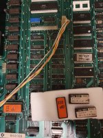
On the bench this time a CBM / PET 8032 which I got a while ago and decided to give a try.. it's my first PET.

Board version is 8032030, it doesn't boot / chirp and subsequently doesn't show any video.

I cleaned it up and replaced the capacitors that were obviously cracked or leaked their insides. If there are others that must be replaced please let me know...

After that I felt brave enough to turn it on and check for correct voltages. The voltage levels seem fine, but don't look too smooth.

I saw this thread (https://forum.vcfed.org/index.php?threads/pet-4016-transformer-question.1238209/#post-1251726) and followed the steps up to checking the CPU and video chip.

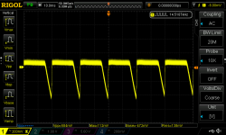
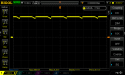
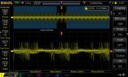
The CPU is alive (I think, at least it goes out of reset) but the video signals look wrong. The only one that looked ok was pin 3 of UC2 (assuming I have a similar board as in the linked thread). Other video signals weren't present or completely off.
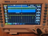
20220420_232446.jpg

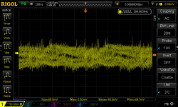
Any idea where to go from here? Also, how do I deal with the unstable 5V? You can see it on the zoomed out waveform.

There are a lot of PET versions out there so it's a bit confusing which guide or manual to follow. Which ICs can I pull and aren't needed for booting the PET? On my board all the 40 pin ICs and ROMs are socketed.

Thanks for your thoughts
 
The Horizontal Drive waveform should be 20 KHz not 3.9 KHz. The 6545 CRT Controller (UB13) is not being initialized at power-up or is not working. Is the chip on a socket by chance so it can be switched easily?

As far as the +5V, let us see the +5 line on the scope with the AC setting and about 0.05 V vertical sensitivity with 10X probe.

No chirp implies that the CPU is not running proper code very long. Bad ROM, bad low RAM, short on data bus, any number of things...It can be fixed.
 
Hello Dave

Thanks for having a look. The CRT controller is socketed, but I have no spare ICs for PET computers.

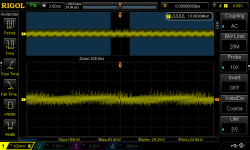
Here are are some measurements of the +5V, taken from one of the 4116 RAM ICs:

DS1Z_QuickPrint5.pngDS1Z_QuickPrint6.pngDS1Z_QuickPrint7.png
 
Hi,

The schematics etc. for your specific machine can be found here: http://www.zimmers.net/anonftp/pub/cbm/schematics/computers/pet/8032/index.html

Note that there are two (2) separate +5V supplies, along with +12V and -5V. All of these are required to be within specification. 4.75V to 5.25V for +5V (nominal) are where the limits are. You have 88mV peak to peak for the +5V rail you measured. That is fine. However, you need to repeat this measurement for the other +5V supply and the +12V and -5V.

Note that the website I specified has various oscilloscope traces identified for the monitor - that includes the expected traces for the video, horizontal and vertical drive signals from the PET logic board.

Incidentally, your PET is different from the one in the other thread, but the principles are similar nonetheless.

Dave
 
Hi Dave

I found that page, but was not sure which schematics apply to my board. Is it 8032029? Some of those scans are also hard to read.

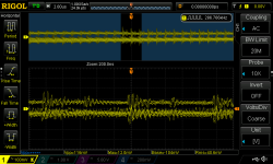
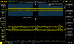
Is it possible the +5V rails are out of spec? They both exhibit the spiky pattern in my previous post when zoomed out. The others are around 200-400mv p-p.

-5V (TP1): tp1.png, +12V (TP2): tp2.png

+5V (TP3): tp3.png,+5V (TP4): tp4.png

 
>>> Is it 8032029?

Yes.

>>> Some of those scans are also hard to read.

Be thankful that we have those!

There is another manual in the same directory (Commodore_8032_Tech_Manual.pdf). But the scans are even worse...

I'll have a look at your photographs presently - I have a meeting to go to...

Dave
 
the +5V rails will be a bit more 'lively' than the others - as they have all of the logic switching devices on them.

The +12V and -5V rails are (in general) used by the DRAM.

From your oscilloscope traces it is TP1 (-5V) that I would be more worried about (at 404 mV pk-pk).

Dave
 
Ok.. starting with the -5V, is there a standard procedure for troubleshooting this kind of problem? Or do I need to replace components one by one?
 
I would start by looking at the capacitors on the input and output of the 7905 voltage regulator (VR1). It is unlikely that be any of the integrated circuits. The ICs produce the current spikes, but it is the capacitors that hold the charge to eliminate/reduce the noise.

The capacitors may have gone open circuit, or have reduced their capacitance so as to be of no use.

You could also try and solder some temporary capacitors onto the output of the voltage regulator (observing the polarity if necessary) to see if that does reduce the measured noise at all.

Dave
 
Yes, I agree with daver, many of the caps on schematic sheet 11 are going bad. Your regulated voltages are too noisy.

The gif scans should be clear. Try another browser if they display poorly.
 
Thanks for the hints.. I have downloaded the gifs, it's alright like that.

I've replaced all the capacitors on the board now. Apart from the pattern on the +5V line, the noise is now at about 80-100mV p-p.

On the -5V it looks about the same at before.. but a bit lower.. at about 200-300mV p-p, depending where I probe. Is that acceptable? I have also noticed that CR2 (one of the rectifiers) gets very hot and the other one doesn't.. is this something to worry about?

Which other component could be causing the noise? A bad IC or any of the diodes/regulators?
 
CR2 getting warm would be normal. That is passing the highest current for the +5V rail feeding all of the ICs.

Those pk-pk figures sound fine to me.

Where are we now with the PET?

Dave
 
If the voltages are acceptable, then the symptoms remain that it doesn't chirp.

Is there a troubleshooting procedure? If there is a document to read I will gladly go through it. Else I'd be happy to know where to start probing.

The CPU has some signals but nothing which suggests code execution. Am I right to assume that if the CPU goes out of reset I can start checking the RAM or ROMs, address lines...?
 
Can you check pin 7 (SYNC) of the 6502 CPU. Is it pulsing? Each high-going pulse of this pin indicates the CPU executing an instruction.

Are you able to program a 2716 EPROM at all? If so, you can download the code for my PETTESTER, burn it into an EPROM and swap it for the EDIT ROM. We can see what we get then.

Dave
 
Yep, it's pulsing. I only have a bunch of 27C512 at the moment. Which type of ROMs do I need besides the 2716 for EDIT / PETTESTER, assuming any of them could have failed? I'll order them in one go then.

Thanks again for the help, happy to make progress
 
All of the other ROMs can be replaced by 2532s. Note, however, that these are getting difficult to find and programming support is a bit variable (especially on modern programmers).

My PETTESTER will checksum the other ROMs, so I would suggest not worrying too much about this to start with. However, my PETTESTER does require the kernel ROM to be at least partially functioning.

You may want to consider one of the RAM/ROM replacement boards that are available? Some of these have inbuilt support for various diagnostic ROM code and a thing called a NOP generator. These fit into the CPU socket.

Dave
 
Ok, I'll start with the PETTESTER ROM. Can I use the CMOS variants interchangeably with the non C ones in the PET? E.g. a 27C16?

And for the 2532, couldn't I just use an adapter, for example this one? https://github.com/ricardoquesada/2732-to-2532
I was convinced that at least one of the C64 and other retro computer stores had them, but I can't find them. If it's compatible I will just use a prototype board and the parts I have lying around until I have a prettier solution.

Before I get a replacement board I would like to make sure that at least most of the other components are working (screen, keyboard). If I have to replace several DRAM chips I'll definitely consider it.

Thanks again for your patience and help, I have the feeling that most of these things are obvious to the experts here but it's new territory for me.
 
I would guess that you can use the 27C16. The C just indicates CMOS - so low power.

Yes, of course you can use an adapter if you wish.

No problem with the helping out at all. It is just nice to get another working PET!

Dave
 
Can I use the CMOS variants interchangeably with the non C ones in the PET? E.g. a 27C16?
As daver says, a 27C16 will work fine. You may also consider a 2816 or 28C16 EEPROM if it is easier to find. It will work as a ROM since the Write Enable (pin 21) will always be held high (disabled).
 
Hello

Good news! I finally managed to burn a 2716 (it was the easiest to procure locally) with my tl866ii+, placed it in the PET and checked the video signals...

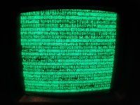
It looked correct, so I plugged in the CRT and this is the result:

20220507_210245.jpg

What does this tell me now? Is it a RAM fault?

In case you wonder about the weird characters, I have no idea what to make of.. here is a picture of the ROMs:

20220507_211931.jpg
If dumps are needed please let me know (some instructions would be nice if there are additional steps to consider)

Do I have to change something in the ROM? I assume I have a 50Hz machine...and the characters should be German.. I think.
The link in the manual is broken (http://cbm-hackers.2304266.n4.nabble.com/PET-50Hz-editor-ROMS-td4658493.html) and I'm not sure if my PET has a CRTC controller or not

Thanks for any advice :)
 
Back
Top