• Please review our updated Terms and Rules here

CBM/PET 8032 not booting

Hugo,

The PET Revealed is one I can remember. I posted an online PDF reference to it in another PET thread. They are all merging into one now! I have so many PET threads on the go concurrently!

Dave
I'm actually impressed that you're handling so much PET support here :)

It's starting to look good. To my surprise, none of the RAM were faulty (at least 7 passes into the test) and the ROM checksum indicate version 4.

Unfortunately, the ROM that seems most important is dead! When I reinserted the original one, the CRT was completely out of sync.

I guess I need a new edit ROM, right? What would you recommend? I will start looking for clues to the one I have...maybe I can read data off it...
 
It's just an off the shelf Hitachi HN462532G EPROM with the label F32 103 on it... I'm building an adapter now to read it, and then make another one for putting a 2732 into the PET
 
It's just an off the shelf Hitachi HN462532G EPROM with the label F32 103 on it... I'm building an adapter now to read it, and then make another one for putting a 2732 into the PET
OK, if you use a 2732 4K EPROM for the 2K EDIT file for UD7, then burn the 2K data into the upper 2K address space and it will work without an adapter in the PET. Note that the 2732 can NOT be used to replace the other 4K ROMs unless you use an adapter socket.

Program the 2K binary file into the 2732 into the upper half of the 4K address space like this:

0000 > leave this lower 2K space blank
07FF > leave this lower 2K space blank
0800 > Start 2K data here
0FFF > End of 2K data

Or if is easier, simply put the 2K image into both the lower and upper half of the 2732 EPROM.
 
>>> I'm actually impressed that you're handling so much PET support here

Usually they come in as ones and twos - but we seem to have four going at the same time at the moment! After tonight it is now down to three - because one has been fixed today...

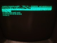
Yours can’t be far away. Any chance of posting a photograph of the screen containing the ROM checksums? Always nice to see a photograph of that.

Did that broken track look damaged by accident or deliberately I wonder?

It will also be interesting to see what is in the EDIT ROM. These were sometimes customised for a particular sign on message at startup etc.

Dave
 
OK, if you use a 2732 4K EPROM for the 2K EDIT file for UD7, then burn the 2K data into the upper 2K address space and it will work without an adapter in the PET. Note that the 2732 can NOT be used to replace the other 4K ROMs unless you use an adapter socket.

Program the 2K binary file into the 2732 into the upper half of the 4K address space like this:

0000 > leave this lower 2K space blank
07FF > leave this lower 2K space blank
0800 > Start 2K data here
0FFF > End of 2K data

Or if is easier, simply put the 2K image into both the lower and upper half of the 2732 EPROM.
Thanks for the hint!
I have to bodge the 21V into the EPROM again as my programmer only goes up to 18V and it's gotten late to do all that, so I'll try burning an EDIT ROM tomorrow
>>> I'm actually impressed that you're handling so much PET support here

Usually they come in as ones and twos - but we seem to have four going at the same time at the moment! After tonight it is now down to three - because one has been fixed today...

Yours can’t be far away. Any chance of posting a photograph of the screen containing the ROM checksums? Always nice to see a photograph of that.

Did that broken track look damaged by accident or deliberately I wonder?

It will also be interesting to see what is in the EDIT ROM. These were sometimes customised for a particular sign on message at startup etc.

Dave

No broken tracks on my PET (wrong thread again ;)). I hope I can get some data out of that EPROM.. I'm halfway through soldering the adapter.

Here's the picture:

20220510_233735.jpg

Time for bed unfortunately.. but thanks a lot for the help and also for providing this awesome testing ROM!

Looking forward to get the PET running again :)
 
>>> No broken tracks on my PET (wrong thread again).

You’re completely correct, it is getting late :) !

I see the German character generator is interestingly different. I was getting confused (originally) about the character before the ‘a’. I am used to that being an ‘@‘ symbol.

>>> but thanks a lot for the help and also for providing this awesome testing ROM!

My pleasure. Glad it has been of use. I must get around to putting a bit more effort into version 5 though to test more of the hardware.

Dave
 
I hope I can get some data out of that EPROM.. I'm halfway through soldering the adapter.
Are you using an adapter for the 2732 in the EDIT (UD7) socket? Then you must place the 2K binary image into the beginning of the 4K EPROM $0000 -$07FF.

With no adapter needed, you must place the image at $0800 - $0FFF. This is possible due to the differences in pinouts between the 2732 and the 2332 ROM.
 
Well, no luck with the PET today... I couldn't manage to burn an edit ROM. Looks like I need EPROMs that are compatible with my programmer.

Reading the ROM contents went a bit better, I attached some of them in case someone wants to explore them.

Will be back when manage to have a functional edit ROM.
 

Attachments

  • CBM8032_F32_edit_ROM_broken.zip
    5.9 KB · Views: 6
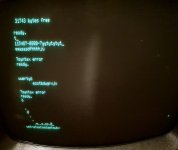
Good news, I managed to burn an EDIT ROM, and the PET boots into Basic (it finally chirped :)):

20220522-004049.jpg
Unfortunately, it's incompatible with the keyboard and I cannot use it properly (can't even tell if all keys are working).... any chances of recovering or reconstructing the broken ROM data?
 
Excellent work!

What EDIT ROM did you burn?

I will take a look at your EDIT ROM dump of your 'bespoke' device tomorrow to see if I can learn anything about it.

Dave
 
I tried both of these:
- edit-4-80-b-50Hz.901474-04.bin
- edit-4-80-b-50Hz.german.bin

The keypresses don't really match with what's on the keys in both cases.

The keyboard is not a business keyboard though, it's a modified Maxi-Switch (?) and the keyboard layout is Swiss German, which explains the character ROM.

Looks like this, but with modifcations:
Found this as well: https://telcontar.net/KBK/Maxi-Switch/6000

How to verify if all the keys work? I don't want to put it together and then find out I have to dissassemble it again... the switches are soldered and the keyplate is riveted to the PCB so the only way of cleaning it is spraying something into the switches. If any of the keyboard experts know what kind of cleaner is acceptable for these let me know.

I'll open a new thread with some pictures, there are more questions I have before the PET is made whole again.

I will take a look at your EDIT ROM dump of your 'bespoke' device tomorrow to see if I can learn anything about it.

Thanks a lot! In the meantime I'll also try to find out more. Any reading material about this EDIT ROM / keyboard concepts to recommend?
 
Use my PETTESTER EPROM.

It has a test whereby it will display the key matrix. This will (a) allow you to test that each key is functioning and (b) allow to to reverse engineer the key matrix so we can modify an existing EDIT ROM if this turns out to be a ‘special’.

This was the screen you had up in post #46.

I can’t seem to find a post of a picture of your actual keyboard. That might also help. Especially if it is a ‘modification’ of the links you have posted.

This page may be a useful “starter for ten” read: http://www.6502.org/users/andre/petindex/keyboards.html.

Dave
 
Last edited:
Ok, I have run a difference between the two sets of EDIT ROMS:

CBM8032_F32_103.bin
edit-4-80-b-50Hz.901474-04.bin

In the former case, is it true that the ROM is 4K?

A 'normal' EDIT ROM is 2K. Yes, I can see some changes above the 2K limit...

I have run a difference and the two sets of ROMs are very similar:

I am going to compare the ROM differences to the disassembled source code for BASIC 4: http://www.zimmers.net/anonftp/pub/cbm/src/pet/pet_rom4_disassembly.txt.

The first thing that I notice is that the initialisation entry point at $E000 has changed from JMP $E04B to JMP $E9A0. This alone is outside of the E000...E7FF limit (2K) so puts the execution outside of a standard EDIT ROM. Of course, this may not be a standard EDIT ROM!

There does appear to be a block of code from $E900 to $E9Fx, so there is something there. Perhaps a bit of disassembly here required?

The first major block of changes is at $E6D0 - and this just happens to be the keyboard decoding table! I note there is a slight difference in the initialisation of the CRTC also.

The remaining changes are 'interesting' as they occur outside the 2K limit. This implies that some of the EDIT ROM (assuming it is really a 4K device) is enabled overlapping the I/O space. Presumably 'unprogrammed' ROM bytes ($FF) do not interfere with the normal operation of the I/O space due to the 'wire-OR' nature of TTL signals.

Just thought I would post this preliminary analysis...

Dave
 

Attachments

  • DIFS.txt
    12.9 KB · Views: 5
I have disassembled the three (3) areas of additional code above the 2K limit - and it does appear to make sense...

I can see that the initialisation entry point has changed and that there are a few 'patches' that been applied to the 'normal' EDIT ROM code to jump into the extended area. These seem associated with keyboard SHIFT character manipulation and the like.

See attached.

Yes, the later PETs had the I/O area mapped from $E800 to $E8FF (256 bytes) with the remaining space either unused (in the case of the 2K EDIT ROM) or used by the 4K EDIT ROM.

I will have a look at the keyboard table next.

I can see that the keyboard mapping is somewhat different - but you already knew that didn't you!

Where do you want to go next?

Incidentally, it doesn't appear as though there is anything wrong with the EDIT ROM you removed (with the label on) - so (my question is) why isn't it working in your PET?

Dave
 

Attachments

  • DIFS.txt
    20.2 KB · Views: 13
Last edited:
It's just an off the shelf Hitachi HN462532G EPROM with the label F32 103 on it... I'm building an adapter now to read it, and then make another one for putting a 2732 into the PET

I am just reviewing the posts in the thread...

You didn't burn it into a 2732 did you by any chance?

A 2732 is no good for the EDIT ROM - it needs to be a 2532 (unless you are using a 2732 EPROM to 2532 socket adapter of course). But I am reiterating what @dave_m has already stated.

Dave
 
Last edited:
It seems as though your "CBM8032_F32_103.bin" ROM contains the CRTC initialisation for one set of PET/CBM 50Hz code whereas the "edit-4-80-b-50Hz.901474-04.bin" ROM contains the 'other' CRTC initialisation for the PET/CBM 50Hz code...

It is interesting (from what I am understanding) that "edit-4-80-b-50Hz.901474-04.bin" appears to work but "CBM8032_F32_103.bin" produces synchronisation issues. Is that statement correct? If so, I am just wondering whether 'transplanting' the CRTC initialisation data from one (working) EDIT ROM to the non-working EDIT ROM might cure your issue?

Dave
 
Hi Dave

I have used a 2732 with a 2k EDIT ROM bin and it worked fine.

It is interesting (from what I am understanding) that "edit-4-80-b-50Hz.901474-04.bin" appears to work but "CBM8032_F32_103.bin" produces synchronisation issues. Is that statement correct? If so, I am just wondering whether 'transplanting' the CRTC initialisation data from one (working) EDIT ROM to the non-working EDIT ROM might cure your issue?
It produces sync issues because it doesn't initialise the CRTC.. when you stick the ROM into VICE all you get are garbled characters, whereas the character ROM works.

Thanks for looking at the code and confirming that it looks ok, this really makes troubleshooting so much easier...and is the clue I needed for the next step forward :)

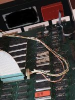
What I didn't mention until now because it seemed irrelevant was that there was a device attached to the inside of the case which didn't seem to do anything in the beginning when I started fixing the PET. Now that you said that the ROM looks ok, I thought I'll reattach it as it's the only thing missing in the configuration. I have cleaned the contacts of the connector thoroughly and plugged it in, and now it boots!!!

Here is a picture of the device which I took before I started the repairs:
8032_cassette_port_device.jpg

Any idea what it could be? Why does it prevent the PET from booting? Can we reverse engineer it before it fails?

Btw I attached a tape drive to test if it works, and some things are already different. Shift Run/Stop causes a "searching for 0:* / ?device not presend error". When type load it finds a program on tape, but then doesn't list or run anything...

Unfortunately I have to go on a business trip and leave the PET be for a few days :/

When I come back I'll open a new thread with pictures of everything.
 
I presume what you are talking about is the "red brick"?

The key thing is - where does the ribbon cable plug into?

A 2732 with a 2K EDIT ROM is fine - providing it is either burnt into the upper half, or burnt twice into the EPROM.

The F32 103 ROM is a 4K EDIT ROM - and burning this into a 2732 will not work. Just want to put this out there...

No problem, I was away on a business trip last week myself... It pays the bills!

Dave
 
Back
Top