• Please review our updated Terms and Rules here

Commodore 1084 (1081) Monitor problem

demonlg

Veteran Member
Joined
May 22, 2016
Messages
521
Location
Italy
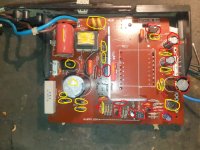
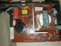
Hi at all, another question for my pieces in collection... I have buyed an old 1084 Monitor (without S on model number) in not working condition. It's arrived 3 days ago and i have opened it for checking. The monitor board don't have any problem, abount 2 capacitors in lost and i have replaced, the flyback is ok, but it is not a most common HR7406 or 7533 model, this board is a 1081 board with more big flyback fixed with screw on the PCB.

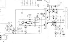
The problem is on a power supply, if i disconnect all cable from it and test it out of the monitor i' don't have the three voltage on output (125v 26v5v and 15,5v), but i have 30v on 125v rail, 6 volt on 26,5 rail and 4 volt on 15,5 rail)
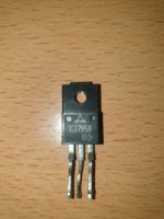
I have replaced all 1n4148 diodes and all electrolityc capacitors, and checked all resistors and other orange not polarizec caps, all are fine. Then i have replaced dhe BUT11AF and the TRIAC buth nothing.

I have suspect for the optocoupler CNX62A because the upper mensined voltage slowing going ap to the mensioned value, i have the 178v con the degause output.
Primary circuit is ok, i have 360volt on big caps and same voltage on the BUT11AF, then i have approximately 300 volt on input of Switching transformer.

The fuse not blown, if i reconnect on the monitor i have the same voltage and the power led coing on slowely, not have any reaction from monitor board because the voltage are loss from power supply.

Anyone have an idea, or anyone have spare powersupply to sell? I will try with new opto coupler but if not resolve i need a chance to repair it.
Exist a replacement modenr power suply for this monitor?

Thanks

Emanuel
 
We need the schematic posted.

Be aware that the psu might go into shutdown mode (protection mode with low output voltages) if disconnected from the VDU circuitry completely by unplugging the cable. That might be normal for it, unless you know for sure that this design of psu will successfully start in the totally unloaded state (without dummy loads), it might or it might not. Do you know for sure that this supply will start up in the unloaded state ?

Also, if there is a fault in the VDU circuitry loading one of its three outputs (most likely the 125v rail), it will also go into shut down mode when plugged onto the VDU as well.

As more and more parts in the psu get replaced and nothing changes, it starts to suggest the problem might not be in the actual psu itself, unless you have plugged another supply onto the VDU circuits and the VDU is actually working ok and drawing the normal currents, have you done that ?

The normal process is to initially locate the region of the fault, then home in on the faulty part after studying the results of tests and experiments on the circuitry. Global parts replacements often lead to a dead end.

The way to check it, initially at least, is to leave the supply plugged onto the VDU circuitry providing some loads, and disconnect just one of its output rails at a time, so at least it has some load on starting.

If it is a case of overload (in the plugged up condition) shutting it down, the common thing that causes it, is a failure in the H deflection system, causing excessive current. This can happen without fuses blowing. I would suggest, if you have not yet confirmed the VDU runs with another supply, as an initial test, just disconnecting the 125V supply feed to the H output stage and seeing if the supply starts up.

If you have confirmed that the VDU runs with another power supply already, I would suggest that the fault finding process on the psu circuitry is done while it is still plugged onto the VDU circuitry, so that it has its normal loads, unless you are able to make a correct dummy load for it.
 
Last edited:
We need the schematic posted.

Be aware that the psu might go into shutdown mode (protection mode with low output voltages) if disconnected from the VDU circuitry completely by unplugging the cable. That might be normal for it, unless you know for sure that this design of psu will successfully start in the totally unloaded state (without dummy loads), it might or it might not. Do you know for sure that this supply will start up in the unloaded state ?

I don't sure if it starts without load, but i remember another one monitor repaired if give output without VDU connnected, but i will try to disconnect the 125v or other two rails by turning on at time, the power supply schematics is in attachment.
Also, if there is a fault in the VDU circuitry loading one of its three outputs (most likely the 125v rail), it will also go into shut down mode when plugged onto the VDU as well.
Probably, but at this time i dont' have a short in a VDU circuitry, but i don't have another PSU to test VDU board, all capacitor and transistor and flyback seem to be fine.
As more and more parts in the psu get replaced and nothing changes, it starts to suggest the problem might not be in the actual psu itself, unless you have plugged another supply onto the VDU circuits and the VDU is actually working ok and drawing the normal currents, have you done that ?
No, i don't have tested with another supply, i dont' have another PSU and other same source to test VDU board, i have suspect now for optocoupler and the switching transformer, but if the transformer was broken I shouldn't even have those voltages out, probably.
The normal process is to initially locate the region of the fault, then home in on the faulty part after studying the results of tests and experiments on the circuitry. Global parts replacements often lead to a dead end.
Yes ok.
The way to check it, initially at least, is to leave the supply plugged onto the VDU circuitry providing some loads, and disconnect just one of its output rails at a time, so at least it has some load on starting.
Ok i will try it.
If it is a case of overload (in the plugged up condition) shutting it down, the common thing that causes it, is a failure in the H deflection system, causing excessive current. This can happen without fuses blowing. I would suggest, if you have not yet confirmed the VDU runs with another supply, as an initial test, just disconnecting the 125V supply feed to the H output stage and seeing if the supply starts up.
Ok try too.
If you have confirmed that the VDU runs with another power supply already, I would suggest that the fault finding process on the psu circuitry is done while it is still plugged onto the VDU circuitry, so that it has its normal loads, unless you are able to make a correct dummy load for it.

Ok, not i don't have dummy load for testing.

In the attached shchematics i have cutted 220v input and i have cuttet to the right at connector output line.
At the monent i have replaced:

All electrolityc caps
BUT11A
BT151-500
All 1n4148 zener diode
Tested all orange caps
The filter input capacitor
Tested all resistor with desoldering one to one
Tested all other diode
Tested the ceramic resistor

Only the transformer and voltage regulator is not replaced, i have another one from a 1084SP1 but it's not have the same pinouts

I don't know what is the correct dummy load to test it, probably a incandescent 220v light bulb connected to the 125v rail with 60W of power consumption?

But now you're making me wonder if the transformer might actually not turn on without load and the problem could be on the VDU board. If it is a flyback problem it is a very big problem because this model is not found in the online shop.

Thanks for response Hugo.

Emanuel
 

Attachments

  • 1081-1084 power supply schematics.jpg
    1081-1084 power supply schematics.jpg
    242.7 KB · Views: 11
If the H output stage is drawing too much current and shutting down the supply, you will often not find this with a meter (unless say the H output transistor is shorted out) and often there will be no short to detect with the meter, it can be a dynamic problem.

When the H output transistor(HOT) is switched on, its collector current rises at a very high rate, equal to the power supply voltage divided by the yoke & Flyback transformer inductance combination at many thousands of Amps per second. But because the HOT is switched on only for around 30 to 40uS, the actual current drawn from the supply might only peak to a few amps, before the HOT is switched off for flyback and the magnetic field reverses and feeds the stored energy back into the power supply via the energy recovery diode.

Therefore a number of faults, including problems with the drive to the hot being incorrect can cause excessive current draw without there being any actual short you would measure with a meter.

I seem to remember, one of these VDU's (I think the same model) had a generic problem they appear to suffer from. The glue around the yoke coils was corrosive toward the enamel copper wire and it caused shorted turns in one of the H yoke coils. This significantly lowered the inductance, caused the H scan current to climb at at much higher rate by the end of H scan time, causing the psu to go into low voltage shut down mode.
 
Thanks Hugo for information of the joke glue....i check it, in effect the internal of monitor are very very poor. I have buyed another 1084-P with the same power supply, and i have found another identical joke on a old tube stored in my garage, if one of joke is ok i will try to replace. The H transistor is ok.

A questions, if i exclude joke, and turn on monitor, i have to see a DOT point at center of screen if its starts? And if i remove flyback?

I have tested the 7812 regulator on VDC board and it's fine too.
 
I have tested resistance with my multimeter the joke coils, one have 14,5 ohm and other 4,5 ohm, then i have tested other two joke of another two same working tube and i have same results.. At this point i have to test power supply with a charge on 125v and if its start the problem is on the VDU Board.
 
I have connected an incandescent 220v bulb to the 125v output of PSU, but it's not start and i don't have any voltage output on all rail, the big capacitor discharge immediatly when i disconnect the power source, then, if i remove bulb i have again 33v on 125v rail, 6 volt on 26,5 rail and 4 volt on 15,5 rail....At this point or is the optocoupler or the switching transformer blowned!
 
I have connected an incandescent 220v bulb to the 125v output of PSU, but it's not start and i don't have any voltage output on all rail, the big capacitor discharge immediatly when i disconnect the power source, then, if i remove bulb i have again 33v on 125v rail, 6 volt on 26,5 rail and 4 volt on 15,5 rail....At this point or is the optocoupler or the switching transformer blowned!
It does sound suspicious that the fault is in the supply. So worth changing the optocoupler at this point.
 
Yes, i have ordered a new one....It's the only component remain old, and the degauss resistor + output diodes (but tested).
 
OK, the optocopuler is arrived, i have replaced it but nothing, the problem is the same, low voltage on output, i have changed also the two little transistor BC337 and BC547, but nothing.
In this week is arrived another 1084 P, same monitor but with philips board, power supply seems to be the same, but not properly the same, it have any plus component and the switching transformer is a different model and have different pinout.
Now this 1084P is working perfectly, probably i change flyback for precautions, but it's working.

I have removed power supply from this working monitor and without charge it's working correctly, i have 145v, 26volt and 15,5 volt on output.

The schematics of 1081/1084 (daewoo board) report 125volt con primary rail for powering the horizontal circuitry but this power supply have 145 volt on this rail out, it's a problem if i exchange the power supply from 1084p to 1081/1084 for testing other not working monitor?

Then, now i have desoldered all diodes on the not working power supply, not the 1n4148 replaced with new ones, and i have tested, all it's ok.... then i have desoldered switching transformer for measuring the coil with multimeter and a little elecltronics instrument i have to test coil and all coils are all ok!

At This point i don't know, only last component to replace are the R104 resistor in parallel of demagnetizer coil...

Last question, schematics reports the BUT11A o AF in a power mosfet position and i have replaced the precedent mosfet with this model BUT11AF, the precedent model is a C3795B.....i don't know if this is a previous monitor proprietary replacement or if it's original... What is the correct mosfet?

Emanuel
 
When you replaced the original BUT11A part (do you still have it ?) what where the physical markings on the body of it it ? can you take a photo of it ?

Since the faulty power supply never recovered, after the replacement of any of the parts you made so far, it suggests that probably none of those parts were faulty. ( Or perhaps, a part was faulty but got replaced with an incorrect one, or perhaps a correct part installed in the wrong orientation, or perhaps a fake part, there are a number of possibilities ).

Can you get the schematic that matches your power supply, put a colored mark on every component you have replaced and post that modified schematic. Also take close up photos of both sides of the faulty power supply pcb and post those too so we can see the state of all the components, tracks and board and try to figure out why the supply is not working properly.
 
I prepare photo tomorrow, but the original (probably not sure) part of BUT11A position are C3795B mosfet.
 
This is the power supply board of my 1081/1084 monitor not working. In RED signed all replaced components, in YELLOW tested component, all resistor not signed with YELLOW are tested.

In next post i attach the photo of mosfet i found first time when i opened monitor and i have replaced it with BUT11A signed to original commodore schematics.
 

Attachments

  • 1084 power supply replaced components.jpg
    1084 power supply replaced components.jpg
    284.2 KB · Views: 10
This is the original mosfet i have found installed and then i have replaced with BUT11A. The working power supply i have use the BUT11A too but the board have similar layout but different component, transformer too! The attached photo is the working power supply.

I don't know if i used the correct schematics or not for checking, only i sure the working monitor is a 1084P (philips mainboard) and the not working monitor is 1081 or 1084D (daewoo mainboard), the two flyback are very different case and pinout.

I have desoldered the transformer for testing coils and i don't find any short on primary and secondary coils, only very low resistence on the (probably) control coils.
 

Attachments

  • mosfet.jpg
    mosfet.jpg
    211.6 KB · Views: 8
  • working power supply.jpg
    working power supply.jpg
    269.5 KB · Views: 8
I have downloaded the datasheet of both mosfet, the C3795B (or 2SC3795B) is with little high max values but very similar characteristics and is good replacement for BUT11A.

Now i have found the BUT11A on schematics, but i have buyed the BUT11AF, only differencies are to packege, the AF is all plastic and isolated from heatsync, the working power supply mount the AF originally.

I don't have any other idea to test and/or repair this power supply, i don't have idea to make another type of test on the transformer, because all other component are new and good, not fake.

Emanuel
 
I'm not sure why you refer to the BUT11A or the 2SC3795 as Mosfets. They are not Mosfets, they are BJT's, might just be a translation thing. Being that they are BJT's, they are very easy to test on a meter. I assume that you understand the difference between a Mosfet and a BJT ?


So many parts have been replaced without it springing to life. This can be a big problem with a non-targeted repairs. Ideally parts are replaced only based on tests which indicate they are likely defective.

It needs a systematic approach, testing with power applied, to try to work out why the supply is in shut-down mode, most likely the SCR crowbar circuit is being triggered. As an experiment you could short out the gate-cathode of the SCR, or remove the SCR, and see if the supply starts. For example if the 18V zener diode in series with the SCR's gate circuit was incorrect or defective, this would cause the supply to go into shut-down mode.

You said that the components in yellow were tested. But I doubt if you could have tested the 18V zener properly. To check this requires a power supply of over 18 volts and a current limiting resistor, to measure the diodes zener (reverse breakdown) voltage. You cannot say the diode is ok, just by checking its forward voltage drop on a meter. This remark also applies to the other Zener diodes in the circuit.
 
Last edited:
Yes sorry, i have mensioned Mosfet but yes it is a BJT.

Next, yes i have tested the 18v diode only with multimeter but i have another little digital component tester, but i don't know if it is good for this purpose, only report a good diode!

Ok, i will try to remove the SCR today, but without this, i have probably all three outputs? If yes the problem is on diode because the SCR is new? (The SCR Diode is the original not replaced)

I'm according to not replace all component in mass, but i have stored original componet.

Thanks for now.

Emanuel
 
Hi Hugo, i have removed the SCR and i have the same issue, 30v on 125v rail, 6 volt on 26,5 rail and 4 volt on 15,5 rail ! If i connect an incandescend lamp con 125 rail i have 0,7v on 125v rail, 0 volt on 26,5 rail and 0 volt on 15,5 rail !

Next step? Try to resolder original 2SC3795B or going to trash the power supply :D

Thanks

Emanuel
Something is stopping the primary circuit from oscillating normally or the feedback via the opto-coupler is shutting down to a low duty cycle. Leave the SCR out for now.

Have you checked the DC voltage out of the bridge rectifier with the meter ?

Double check both the transistors and every component there on the primary side.

With the meter,can you check the voltage across R117 to give us an idea of the opto-coupler's LED current ?

Also check the base and emitter voltage of transistor TS117, with the meter, this controls the opto-coupler.

Have you checked the continuity of the inductors S131 and S136 ? They both should read a very low Ohms value on the meter.
 
Last edited:
Something is stopping the primary circuit from oscillating normally or the feedback via the opto-coupler is shutting down to a low duty cycle. Leave the SCR out for now.

Have you checked the DC voltage out of the bridge rectifier with the meter ?
I have about 300v cc at big caps pins
Double check both the transistors and every component there on the primary side.
can i do....
With the meter,can you check the voltage across R117 to give us an idea of the opto-coupler's LED current ?
can i do...
Also check the base and emitter voltage of transistor TS117, with the meter, this controls the opto-coupler.
can i do...
Have you checked the continuity of the inductors S131 and S136 ? They both should read a very low Ohms value on the meter.
yes both are ok, one is in parallel with a diode in front of bjt, and one is at bottom of transformer in parallel of a resistor, i have desoldered both and tested.

Today i check other your questions

Thanks
 
Back
Top