- VCF South West - June 14 - 16, Davidson-Gundy Alumni Center at University of Texas at Dallas
- VCF West - Aug 2 - 3, Computer History Museum, Mountain View, CA
- VCF Midwest - Sept 7 - 8 2024, Schaumburg, IL
- VCF SoCal - Mid February 2025, Location TBD, Southern CA
- VCF East - April 2025, Infoage Museum, Wall NJ
-
Please review our updated Terms and Rules here
You are using an out of date browser. It may not display this or other websites correctly.
You should upgrade or use an alternative browser.
You should upgrade or use an alternative browser.
Commodore 1084 (1081) Monitor problem
- Thread starter demonlg
- Start date
I have found an 8,2ohm resistor same type in another fault monitor board, and replaced it, now i have power at junctions of components R462, C462, R461, C461 and T401, about 24,5 volt, and now i have signal on connector of T461, about 54v with scope, try to attach photo...
Don't have attached photo but seems is a composite square signals
Don't have attached photo but seems is a composite square signals
Last edited:
daver2
10k Member
It is all going in the right direction!
if you have the heater and -20V rail then the high voltage output stage is at least partially working...
Dave
if you have the heater and -20V rail then the high voltage output stage is at least partially working...
Dave
daver2
10k Member
Great news...
Now we can see the problems at least!
Dave
Now we can see the problems at least!
Dave
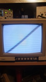
Then, it turns on, with brightness and contrast at minimum on the front you can see it as in the attached photo, if I raise the brightness and contrast a little you can see the image of the C64 under the retrace lines but very slight as an image because ' it is as if the gain was at maximum, but this flyback transformer doesn't seem to have an adjustable gain, or maybe I don't know where the trimmer has been positioned.
I kept it on for a few seconds because it seems that the brightness increases more and more but I'm not sure about this, maybe I don't give enough time to warm up the tube, but I wanted to avoid damaging something else.
The fact is that you were right, it's not the flyback, or maybe we still don't know for sure, the EHT is there!
Attachments
daver2
10k Member
OK - so I need to find the EXACT service manual related to your monitor.
Can you tell me EXACTLY what the part number of your particular monitor is - or point me to the service manual please.
Dave
Can you tell me EXACTLY what the part number of your particular monitor is - or point me to the service manual please.
Dave
At the rear of case a label says Type 1084 without other lecters or number or simble.
In front same 1084. I have a service manual of this and report similar to 1081 model, all the boards photo in this manual are the same of my boards, but is big to attach here.
In front same 1084. I have a service manual of this and report similar to 1081 model, all the boards photo in this manual are the same of my boards, but is big to attach here.
I have retreived links on zimmers.net:
daver2
10k Member
Somewhere within the manual it must describe what all of the on-board preset resistors do?
Dave
Dave
daver2
10k Member
Thanks,
The manual seems to want a fairly accurate 125 Volt DC rail from the Switch Mode Power Supply. It might be sensible to just re-measure that again with your multimeter. I wouldn't, however, adjust anything just yet though.
I think we need @Hugo Holden to have a look now before we go any further.
I suspect Hugo will know exactly what to look at...
Dave
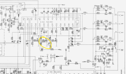
I have found on schematics the variable resistor for the contrast, but probably is this the front panel regulation, i don't have find the Bright regulator at the moment, but all other one on schematics.
This monitor have a FOCUS regulator soldered on the neck board and do not on top of flyback transformer, but i don't say where ise the GAIN of B+! At the right of focus regulator on the neckboard i have another regulator, big to all other one, in last post attached manual is visible, i don't know if is the GAIN, and i don't know if precedent proprietary, when tryed to repair the monitir, have touched it, i'm not!
In fact, precedently of all discussion, when power supply results not working, i have moved little the trimmer on power supply, but i have the 125,5cc on output, i don't have measured it now with all connected.
Emanuel
Attachments
daver2
10k Member
I am sure Hugo is going to suggest measuring the voltages on G1 and G2.
G1 (pin 5 of the tube) should be around -20 Volts. G2 (pin 7 of the tube) should be around 381 Volts - so I wouldn't go poking around there unless I had good leads on my multimeter AND a safe way of measuring this voltage.
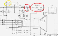
Also of interest is that the +125Volt supply enters the tube PCB on M6 pin 3. This is referred to as "+125" on the schematics; but it also goes via inductor (S717) and a capacitor (C717) to become a 125V supply (referred to as "+125A" on the schematics) for feeding the R, G and B cathode circuitry. I wonder if C717 is in distress and this voltage a bit low?
Hugo is the "monitor main man"...
Dave
G1 (pin 5 of the tube) should be around -20 Volts. G2 (pin 7 of the tube) should be around 381 Volts - so I wouldn't go poking around there unless I had good leads on my multimeter AND a safe way of measuring this voltage.
Also of interest is that the +125Volt supply enters the tube PCB on M6 pin 3. This is referred to as "+125" on the schematics; but it also goes via inductor (S717) and a capacitor (C717) to become a 125V supply (referred to as "+125A" on the schematics) for feeding the R, G and B cathode circuitry. I wonder if C717 is in distress and this voltage a bit low?
Hugo is the "monitor main man"...
Dave
I moved the G2 trimmer a lot counterclockwise, I also saw that I have a bad contact on the M6 connector, it's slow and often doesn't turn on the tube. Yes I have seen both the inductor and the capacitor in fact I would like to check them, they are directly connected to pin 3 of the M6 connector where the 125v arrive. I have moved the brightness and constrast in front panel to the center position, now try to setting G2.