• Please review our updated Terms and Rules here

Commodore 1084 (1081) Monitor problem

I was also getting a little baffled in following the logical progression of what was going on...

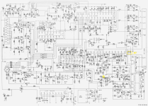
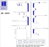
Thanks for the schematics - they will be helpful.

First thing when measuring the heater voltage - have you got your meter set to AC or DC? What voltage range?

Dave

Hi daver, ok for baffing, probably my english and my progression to check problem is wrong.

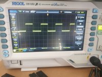
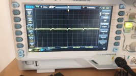
I have setted the meter in DC mode for heater measuring and same for 125v! From flyback datasheet in effect the output is a only positive waveform...i have to measure it with AC mode?

The 125V DC is came from PSU, The 265V DC signed on schematics for me is wrong, because on PSU schematics report 26,5v and not 265v !!! It's correct my observation?

I don't have measured the 12v on IC 403 (L7812 regulator) but try to test it.

Emanuel
 
The heater supply is AC not DC. So you need to set the meter to an AC range to measure that voltage. I suspect it won't be there though - but it is worth checking it all the same.

You are correct about the 265V verses 26.5 Volts! An error on the schematic... You are correct, this should be 26.5V DC.

The first thing to do is to measure all of the 'fixed' power supplies in the monitor. No voltage = not working!

The next thing is to 'divide and conquer' by measuring signals at key points (for example IC402 TDA2595 pin 4). This should be the HORIZONTAL SYNCHRONISING pulse - with a video signal fed into the monitor of course. You will need to measure this with your oscilloscope. It is a fairly low voltage (< 20 Volts). If you don't have a signal here, the problem is ahead of this point. If you do have a signal here, the problem is afterwards.

I would also checkout R469 (12 Ohm 5W resistor) with the power OFF and using your multimeter set to measure resistance. Anything that is a high power device could be a suspect (especially hot resistors). In operation, one side of this resistor should have 125V DC on it. This is the power supply for the line output stage.

Dave
 
The heater supply is AC not DC. So you need to set the meter to an AC range to measure that voltage. I suspect it won't be there though - but it is worth checking it all the same.
Yes, my error, the output of fbt is without rectifing and for this is an AC voltage, sorry i try to measuring again in AC.
You are correct about the 265V verses 26.5 Volts! An error on the schematic... You are correct, this should be 26.5V DC.
Ok. I try ro measuring it again with all connected.
The first thing to do is to measure all of the 'fixed' power supplies in the monitor. No voltage = not working!
yes!
The next thing is to 'divide and conquer' by measuring signals at key points (for example IC402 TDA2595 pin 4). This should be the HORIZONTAL SYNCHRONISING pulse - with a video signal fed into the monitor of course. You will need to measure this with your oscilloscope. It is a fairly low voltage (< 20 Volts). If you don't have a signal here, the problem is ahead of this point. If you do have a signal here, the problem is afterwards.
Ok, i try to connect my c64 with luma croma input, but i don't know if the switch settings on front and rear panel is ok (cvbs/lca on rear and cvbs/rgb on front, try with the other working monitor firts and then check the sync pin on IC402.
I would also checkout R469 (12 Ohm 5W resistor) with the power OFF and using your multimeter set to measure resistance. Anything that is a high power device could be a suspect (especially hot resistors). In operation, one side of this resistor should have 125V DC on it. This is the power supply for the line output stage.
I have measured the resistor and it's ok 12ohm.
 
Ok, first i have measured all fixed power supply in the monitor with all internal cable connected and:

Measured on video board soldering point of wires from PSU

PSU 125v out =125,5v
PSU 26.5 out = 22,5v
PSU 15,,5 out = 13,5v

L7812 pin 3 out = 11,5v

Measured on soldering point at the bottom of flyback transformer

HEATER pins = 0v in AC mode and tube not glow up


I hadn't noticed that, when I turn on the monitor I hear the classic EAT startup sound (classic whistle), but I don't know if it's actually him or the PSU startup, it only makes one whistle at startup and then it ends.

I have to test the TDA2595 but is in a uncomfortable position of board and I don't have the possibility to test the pin under the solder side and not even the component side, I should completely extract the board from the case.

But the fact remains that I don't have voltage on the heater.

Attached the schematics of pinouts of flyback
 

Attachments

  • 1081 flyback pinout.jpg
    1081 flyback pinout.jpg
    70.5 KB · Views: 7
Those voltages look OK (to start with).

The high-pitched whistle could be either the switched mode power supply or the EHT. It probably goes out of your hearing range as it starts up.

If you have no heater voltage, it is likely that you have no EHT and none of the other voltages derived from the Line Output circuitry.

IC402 pin 4 is wired to one end of R448 and one end of R451. Find out (using your multimeter on resistance with the power OFF) which end of these two resistors are connected to IC402 pin 4. Either attach your probe to one of these resistors (if that is easier) or solder a short piece of stiff wire onto the resistor lead to act as a convenient probe attachment point.

Make your life easy (and safe).

I also attach an insulated wire to the point I wish to probe (and a black insulated wire to 0V/GND) and bring these completely out of the monitor chassis to the outside world (terminating in a 'chocolate block' connector with some stiff, solid-core wire to act as a probe attachment). That is as safe as houses then to probe!

Dave
 
Ok Dave, i prepare wire for testing then try to put input signal from C64 and check the TDA pins.

How can i measure the voltage across the horizontal transistor? One wire to GND and other wire on collector or pin 18 of EHT?

Can I measure the other EHT voltages 175vpp and 235vpp? GND to pin 4 then other wire to pin 12 then to pin 8?
 
Let's just take it one step at a time shall we?

We need to be careful where we poke our oscilloscope with the high voltages present (especially the back emf). We don't want to destroy the oscilloscope do we?!

I would also like @Hugo Holden to check off on what we are doing on the high voltage end of this beast :)...

First, let's make sure we have a HORIZONTAL SYNCH. signal to drive the circuitry.

Dave
 
Last edited:
Let's just take it one step at a time shall we?

We need to be careful where we poke our oscilloscope with the high voltages present (especially the back emf). We don't want to destroy the oscilloscope do we?!
Ok, sorry Dave! Not the scope is new -:)
But, where i connect the groud of scope? Chassis of monitor or other point?
I would also like @Hugo Holden to check off on what we are doing on the high voltage end of this beast :)...
Ok
First, let's make sure we have a HORIZONTAL SYNCH. signal to drive the circuitry.

Dave

Ok, i try tomorrow, with sun light in my room, to solder wire to the sync.
 
Last edited:
It looks like the chassis is connected to 0V from the schematics, so that should be fine.

Where did you connect the negative lead of your multimeter to when you took the DC voltage measurements then?

Dave
 
I have connected the lead on the shield wire of tube first, where a black wire start to going on gnd of chassis, in second times at the ground of power supply, the value are the same.

I'm now working to solder wires for sync testing.

0v for ground of scope, ok i check where is on schematics.
 
Last edited:
Ok Dave, i have soldered wire on pin4 of TDA2595 for scope probe and ground scope connected to LCA ground input, the result is this attached file of scope screen, setting on scope are 1v and 20uS scale.
This is with C64 turned on and connected to the LCA input of the monitor, and monitor turned on.

I read on scope 15,6 khz and peak of 2,12v, seems to be fine or not?

Emanuel
 

Attachments

  • signal on pin 4 of TDA2595.jpg
    signal on pin 4 of TDA2595.jpg
    246.2 KB · Views: 5
Last edited:
Excellent - looks good to me.

You at least have a signal there...

Let me have a think where next...

My gut feeling will be the collector of transistor TS461 (at the junction with C464, T401, D461 and C463).

This is supplied from the 26.5 Volt rail (now we know it is not 265 Volts!) - but there could be a bit of back emf induced because of the action of transformer T401.

Assume this signal is going to be in the order of 60V - and set the oscilloscope up accordingly. You can always reduce the Y channel Volts/division to get a larger signal on the oscilloscope screen. We are looking for a signal at the same frequency as the horizontal synchronisation pulse again. Post a picture of what you observe.

When the transistor is OFF - this voltage should be at it's highest. When the transistor turns ON, this voltage should fall almost to 0V.

Dave
 
Last edited:
You're telling me to measure at the junction marked here right? Always with C64 on and input signal active?

If Yes i have setted scope to 50v and then to 100v but i don't have any signals here!

The white wire soldered is my scope probe.
 

Attachments

  • 1084_0001_t461 collector point.png
    1084_0001_t461 collector point.png
    1.5 MB · Views: 8
  • Immagine WhatsApp 2023-02-05 ore 14.35.15.jpg
    Immagine WhatsApp 2023-02-05 ore 14.35.15.jpg
    377 KB · Views: 7
Last edited:
Sorry, i have setted the scope voltage to 1v again and the signal at this point is this attached. The Frequency readed is 15,6 Khz but not very stable, have a peatk to 20khz or 18khz then again 15,6 khz, this with or without C64 signals, and about 600mV.
 

Attachments

  • signal on T461 collector.jpg
    signal on T461 collector.jpg
    196.2 KB · Views: 2
Last edited:
>>> You're telling me to measure at the junction marked here right? Always with C64 on and input signal active?

Yes.

>>> If Yes i have setted scope to 50v and then to 100v but i don't have any signals here!

You are turning the knob the wrong way. If you can't see a signal at 50V - you will not see it at 100V!

Try turning the knob SLOWLY the other way (e.g. 30V or round about there).

Dave
 
>>> Sorry, i have setted the scope voltage to 1v again and the signal at this point is this attached:

That is a very small signal. I am expecting it to be a bit higher than that...

Can you measure what you have at the junctions of components R462, C462, R461, C461 and T401 please.

Let's make sure this part of the circuit has some DC voltage to drive it...

Dave
 
For now, at positive of C461 and C462 i have 0 volt!

Yes confirmed, at the junctions of components R462, C462, R461, C461 and T401 i have 0 volt!
 
Last edited:
OK - we are homing in.

Can you measure the Voltage on the two (2) leads of R462 please.

Black lead of the multimeter on 0V/GND and the red lead of the multimeter first on one lead of R462 and then the other lead of R462.

Multimeter set to DC Volts (to measure approximately 30 Volts).

Dave
 
Yes i have measured it before your message, seems to be broken R462, i have 26,5 volt on pins direction to PSU and 0 volt at the other pin to C462!

Mmmm i have to found an 8,2ohm resistor............ I have new only 10 ohm...
 
Last edited:
>>> seems to be broken R462, i have 26,5 volt on pins direction to PSU and 0 volt at the other pin to C462!

Ahhh!

Perhaps a replacement called for?!

There could be two other scenarios:

1. Transistor TS461 is short circuit - thus all the voltage is dropped across R462. Unlikely.

2. R462 died because of a short circuited transistor TS461.

Buy more than one replacement resistor - just in case...

Do you have the parts list for the monitor? Check the parts list for the wattage. Too small a wattage for the replacement will cause it to burn out. Too high a wattage for the replacement will cause it to not protect the circuitry. These resistors are protection devices. Does the manual indicate what the triangle and exclamation mark symbol means?

Dave
 
Back
Top