• Please review our updated Terms and Rules here

Commodore CBM 2001-16N - BIG MESS!

OK - having gone through some more of the EDIT rom you posted in #16, it has been slightly modified to say

##GUTEN TAG JUERGEN! ## on boot. It them makes some calls to a Custom ROM located in the $Axxx slot.

In Particular it makes a call to $A300 instead of calling $FFEA (Update Clock)

Also the "LOAD RUN" text is replaced with SYS 41802

What ROM was in the $AXXX address socket ?
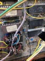
 
Thinking more about the contents and functionality of these ROMS, it would be good to see all the add-on ROMS this PET had installed (especially as this has been so heavily customised) - before considering the effort required to return the add-on board and get it going.

The Edit rom you posted is almost identical to the BASIC 2 EDIT rom with those modifications. The 40 column Basic 4 EDIT rom is very different.
 
OK - having gone through some more of the EDIT rom you posted in #16, it has been slightly modified to say

##GUTEN TAG JUERGEN! ## on boot. It them makes some calls to a Custom ROM located in the $Axxx slot.

In Particular it makes a call to $A300 instead of calling $FFEA (Update Clock)

Also the "LOAD RUN" text is replaced with SYS 41802

What ROM was in the $AXXX address socket ?
That´s really interesting. Now i know the first name of the pre- owner. Obviously a german guy named Jürgen :D
What i found in the ROM sockets D4 and D3 is another mystery - see attached photo. Both chips on the bottom i still have - SRAM HM6116LP-3. Thats the type of RAM i found in the VIC20. Unfortunately i still dont have the chips stacked on the top - some sort of TTL (74-XXXX).
Does it makes sense to you?

By the way - i am not planning to re- install the graphic board. If anyone wants to play with it I can ship it to her/him for the shipping costs only. I want to preserve the Computer as original as possible!

ROM sockets D6-D3.jpg
graphic board.jpg
 
It looks like the guy put in 2K RAM chips in those spare ROM sockets. He must have modified pin 21 which on the board is wired to +5V, but the RAM chip needs write enable. As those two sockets are not utilized in BASIC, they are probably not doing any harm, but I would remove them as it looks like they can short out something at any moment.
 
What EDIT ROM is in the system now? You should put in the standard one for your configuration: 901447-29 for BASIC 4 no CRTC 40 column normal keyboard. Have the system set up for BASIC 4 ROMs.
 
Today I programmed a complete set of BASIC 2.0 ROMs. They all installed now. When running the Pettester from Daver2 in the Edit Rom socket all tests are fine and the ROM checksums are correct. The latest petester revision shows them and in Dave's documentation there is a table with the reference. Therefore I am confident that my ROM set is fine apart from the Edit ROM. Still got my Basic 4.0 ROM set secured in my cabinet;)
 
Hi, i am afraid i still need your support. As you can imagine deliveries in these days can take forever. So, i still did not get my 6522 replacement to fix the read/write issue for the cassette tape.

In the last days i was busy with the VIC20 from my friend which is also faulty (black screen). I could "borrow" the 6522 chip from there for my PET. Unfortunately it was not socketed. But i still got a lot of sockets and I like soldering :D

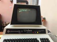
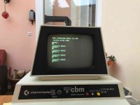
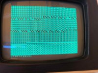
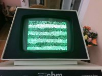
So, i de- soldered one 6522 out of the VIC20. Then i realized the legs from that chip were not long enough to get good contact in the C5 socket of the PET (the last 40 pin original one from Commodore). So, i replaced this socket. Maybe something went wrong here. Because since that exercise i dont get a blinking cursor anymore. It always boots with the @ symbol. I can enter characters but it makes no sense because i always have a fault character in the line. When just pressing ENTER i get an "A" and then a "B", a "C" and when at the bottom on the screen suddenly the screen is filled with inverted characters. Please have a look to attached photos. Has anyone seen this before?

I looked for broken traces, missing connections. Everything looks ok. I checked continuity on C5 and C7 - ok. I replaced the 6522 - no change. I switched C6 with C7 - no change.

What is causing this? Is the Keyboard Decoder (C9) not working properly anymore?

What is also strange - i checked with Dave´s Petester V4 which used to run to the end of all tests before. Now it stucks at the VDU test. It looks that it passed the VDU Test but why it is not going further?

Boot Screen.jpg
Just pressing enter.jpg
end of screen.jpg
petester v4 hanging on VDU test.jpg
 
If the characters are ALL displayed correctly on the screen this means that the CPU can correctly write to the video RAM (and the results are correctly displayed) - but it is likely that the CPU is not correctly reading the values back FROM the video RAM.

That would be my guess.

It is too much of a coincidence that it went wrong concurrently with you swapping out a socket though...

Dave

Good Morning Dave. Again - You pointed me in the right direction!!! I was looking so deeply in other things which were ok. It is solved now and the reason is really odd.

In the very beginning of this thread (posts 34, 38,39,40) there was a discussion about a strange jumper i found. This jumper to GND pulled A5, Pin 9 to permanent low. I thought it belongs to the Video Board modification which now turns out being right. Back in time i was a bit confused about that jumper and i did cut it intially and re- soldered later before Mike S. finally said it should be disconnected. But i kept it connecting. Now, what is really odd: When i quickly re- soldered that jumper on GND i did use my mobile (battery driven) soldering iron. This soldering joint was not good and became loosen over time which i did not notice. But therefore i got a running PET with blinking cursor last week.
Obviously when i changed the socket for the 6522 VIA chip the jumper was getting a better contact again and caused that missing cursor issue.
Now, when i started troubleshooting i found this losen wire and re- soldered it nicely and made the thing worse - Haha. :D

Anyway- now i get a blinking cursor und furthermore i can now write to cassette tape! With the 6520 from the VIC20 :D At least after some seconds writing it stops and says ok.
However the program i wrote to cassette tape i cant read back in. But i could read a program written with my C64. So maybe there is still something not 100% right....

But - you know being locked home in these days i am happy to got something to solve :D
Maybe i should tell my girlfriend to secretly cut a random wire in the unit so i have to look for another problem. Haha. Just joking :D
 
If I recall correctly, the wire was related to blocking the read of the video RAM while the external board video board RAM was attached.
It sounds like you might need some soldering lessons. You should be able to tell the difference between a gob of solder and a proper joint. Just because it is working is not a good criteria.
To do a good job requires a clean tinned tip and fresh flux ( not plumbers flux please ).
Dwight
 
Yes, you don't want to go connecting that pin to GND without a good reason :). As Dwight correctly states, that pin being low prevents the CPU from reading the contents of the video RAM. No wonder my PETTESTER was complaining...

By the looks of it, a WRITE by the CPU would have occurred to both the PET original screen memory AND the bolt-on video card. But a CPU READ must only come from one or the other (otherwise you would get bus contention and the CPU would read garbage). This must have been the way the original owner had disabled the PET video RAM.

As to the cassette read/write issue. The cassette write for both of the recorder/players is sourced from pin 13 of the VIA (6522) UC5.

The READ lines, on the other hand, are processed separately.

Cassette #1 (J3) PIA (6520) UC7 pin 40.

Cassette #2 (J6) VIA (6522) UC5 pin 18.

If you checkout the schematic (http://www.zimmers.net/anonftp/pub/cbm/schematics/computers/pet/2001N/320349-3.gif) you will see there are a couple of links on the PCB. Are these intact or not? Just a thought.

Have you tried writing a tape via (say) cassette port #1 and then trying to read it via both cassette ports #1 and #2?

SAVE "FRED"
LOAD "FRED"
LOAD "FRED",2

You could also hit 'PLAY' on the cassette drive and monitor the appropriate pin(s) with an oscilloscope or logic probe (PIA and/or VIA) to see if any signals are present. The signal level from the cassette should be 5V or so - so it should be obvious. To get a comparison, perform a SAVE from the PET and monitor the cassette WRITE signal. It should be similar on a LOAD/READ.

Keep your girlfriend well away :)! They have a nasty habit of trying to dispose of vintage computers...

Dave
 
Last edited:
Hi.

I am considering this Pet as FIXED now although i could not check the IEEE-488 Interface and Parallel User Port yet. Both of the last issues have been solved by replacing the 6522 VIA Chip. The system is now running its original Firmware (Microsoft Basic 3.0) and can read/ write from/ to cassette tape.

The tape reading issue i was able to solve by:

- cleaning the tape recorders read/ write head
- Adjusting the Tape recorder Azimuth screw using the C64 and the SW "CASSETTE-AZIMUTH by H. Diebeck"
https://csdb.dk/release/?id=49944
- using another tape

Again i want to say a BIG THANK to you all. Especially to Dwight for his patience to teach me in electronics and scope handling (lets say i now reached the next grade). Special thanks also to Daver2 and his nice Petester. And also to dave_m, MikeS, AndyG and all the others who gave me nice support in repairing my old Commodore :D
For some of you I may appear quiet obtusely but please note my background is mainly mechanics and i started to work on electronics in this level only few years ago.

I did really enjoy this journey of troubleshooting and i learned a lot. You are a great forum!!!! I will certainly stay here and will try to help others so far i can.

And one more thing....about my soldering skills;)
I feel confident in de- soldering and soldering and i like this kind of tasks because i am a mechanic. For me it is very satisfying. And yes i always got a clean tinned tip and fresh flux. I know the Basics! And yes, i messed up one important soldering joint and Dwight (as my new Internet teacher:)) has the right to criticize me. But my other joints are perfect and conductive. I did tell my story to help others not to repeat my mistakes!

I hope, after this crisis i will have the opportunity to come back to California to show him. This is not unlikely as my company got a factory in Carlsbad :D


Space Invaders running.jpg
 
I enjoyed the hunt.
Here and at work, I always try to clearly convey my thoughts, in a clear way. It is difficult but I am learning as well. As I'm getting closer to retiring, my boss wants me to pass on my thinking and problem solving to the next generation. I need to pass on information clearly and without getting frustrated. When first asked to do such, I didn't know how to begin.
Anyway, I can sum it up in a few words.
First what is it suppose to do that it is not.
What do I expect to see at each point in the circuit, based on what I saw last? Remember, it isn't working so I shouldn't expect to see that it is.
When possible run experiments to better understand the problem.
Working with some parts of computers is relatively easy. One sees, such and such on one side of a device one thing but on the other side it isn't what is expected. This works looking forward and backwards.
Micro processors make it a little more difficult. Being able to write and execute test code is always one of the main ways to deal with these machines ( remember, experiment! ). Dave's test ROM is great for this.
Years ago, I was responsible for test procedures of a particular board at Intel ( what was called the analog board for the floppy controller ). I was tasked with showing the technician on the line how to trouble shoot them using a pile of what was called "yellow dot board inventory". ( we put a yellow dot on failed boards ) I used the meter and scope to show the tech what to look for at each point of the design. I thought I was doing really great as we were zipping through the boards as many had the same problems but I though I was doing great on showing what to look for. When done, I realized that I'd wasted my time. The tech was just writing down a list of things to have reworked on the board. No symptoms, just a list. D45, D16, U34 and so on.
He was creating an easter egg replacement list.
This is why you'll see me get frustrated when I see things like "I replaced all the capacitors and it is still broken". It is like saying "I replaced all the tires on the car but it still won't start".
When I help, I try to make it a learning experience for me and for the person that is doing the looking. I try to not do too much of "just show the picture" but also make sure to include what it is suppose to be doing or what is expected and why.
I suspect that is what I forgot to do with the tech. I should have been spending more time analyzing the design with him so he'd learn how each part worked or didn't.
So, as I say, it is a learning experience for me as well. It is helping me at work to be able to teach others how I solve problems so I won't be just leaving a big hole when I leave to retire.
Dwight
 
Last edited:
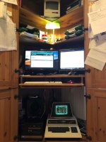
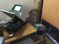
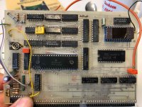
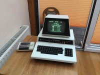
I thought it would be nice to share some impressions from the Unit before, during and after repair. The first photo shows the Pet at its new permanent Home - just below my Home Office desktop! Always ready to play a Space Invaders session :D
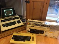
My next project is on the second photo. The "Volks Computer":cool:

Pets new home.jpg
Father and son.jpg
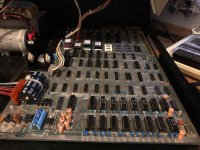
Mainboard after restauration.jpg

And hereby some older photos:

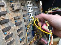
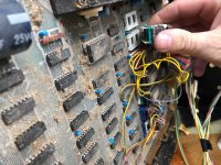
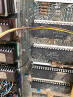
mainboard before #1.jpg
mainboard before #2.jpg
mainboard before #3.jpg
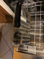
Pet in Dishwasher.jpg
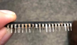
dead 6502.jpg
workbench.jpg

best regards
Denis
 
Back
Top