• Please review our updated Terms and Rules here

Commodore CBM 2001-16N - BIG MESS!

miata

Experienced Member
Joined
Sep 18, 2019
Messages
197
Location
Dresden, Germany
Hi,

Greetings from Germany :)

i already read some posts here about troubleshooting the old Commodore PET. I really love the design of it and was able to find an old unit (likely 1978) in my area. But it was in a horroble shape especially inside. The computer was obviously a home for mice for years! But i could not leave it there. After cleaning up a bit i started troubleshooting following some advice what i found across the Internet. The unit is somehow special. The pre owner (died some years ago) did a lot of modifications on the unit. He stacked 2 ROM´s on each other for each slot and routed the associated VCC supplies to a switch on the front of the unit. Additionally he added a Board with the MC6845P on the extension port. From there the Display is connected. He also added another 16 kb of RAM.

My plan is to put it back to an original state - whatever this could mean....

Before deeper touching the electronics i was able to power up the CBM and got the garbage display on the Screen. At least the Display is working :) Obvioulsy the Character ROM is also working othertwise i would not see any proper characters, right?

First i measured the Voltages: 17,36 VAC / +5,00 VDC / -5,42 VDC / +11,90 VDC
This is not so bad, correct?

I have checked the 6502 in my Apple 2 - got only question marks in that unit - so obviously dead
I already replaced a known good one - CLOSED

I was able to download the ROM Software from the Top EPROMS (BASIC 4.0) and verify with the files on Zimmers.net
They all look ok apart from the EDIT Rom. This seems to be special. However i downloaded a backup from it and put this back in the CBM. I feel confident all ROM Software is ok.

I proactively replaced 8x RAM by 4116 units to have some spares left for the further troubleshooting.

I also ordered 2x 2114 Video RAM to play with it.

I did check continuity across all 16x RAM chips and found 7 bad sockets and underneath lifted traces (also happened to me while removing them!) Now, the continuity check is ok - CLOSED

I did check continuity across all 7 ROM sockets and found on bad socket. Replaced and ok now. Just found out that the pre owner did cut the jumper between Pins 21/24 (VCC +5VDC) on D3, D4, D5 - still need to fix that

I was hoping that i get at least a different garbage screen but NOPE! The same picture, same characters :-(
I was hoping to use David´s PETTESTE2K (Version 03 beta) to get now a better idea - NOPE Same story :-(

But i get a different picture when i replace the Video RAM by the 2x new ones i received thius week. The screen looks different but still not what i would expect according David´s Manual.

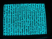
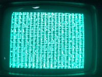
NOW - my question is how to go on with the troubleshooting. Can you please tell me what screen looks more "normal" thus which Video RAM is the better one? I have attached some pictures.

Best regards
Denis
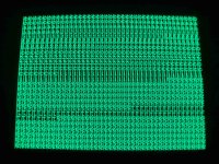
Garbage new VIDEO RAM.jpg
Garbage original VIDEO RAM.jpg
original as get.jpg
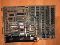
display board.jpg
 
Hi Denis,
Welcome to the Vintage Computer Forum - Commodore Section.
It looks like your main board has been modified. Your ROM sockets seem to have adapters to use perhaps 2732 EPROMs, and the video control is using a special board using a 6845 CRT Controller to replace the existing video control logic on the board as it perhaps failed in the past.

Neither of the video photos look like the proper random characters that should come up so your character generator may still be in question. What were the original ROMs 6540 or 2316 or 2332 chips? The fact that you have a raster scan is a good sign your video mod is basically working, but a lot of checking may be needed.

If your video RAMs are on sockets, remove the 2114 chips and see if you get a proper checkerboard pattern. With the character generator removed you should get a white screen or a blank screen but the raster will be seen. Is there a schematic for the special video board? Be careful removing ICs from sockets. It is easy to bend the pins. Do you have a good chip removal tool? The board looks in bad shape. Was it stored outside?

HI Dave, thanks for your suggestions. I found the CBM stored in a old house under construction. It looked like it was there for longer time. Unfortunately i dont have any history as the pre- owner already passed away.

The Character ROM seems to me the only original ROM chip. All the others are 2732 and 2716 EPROM´s.
When i removed the Character ROM one leg broke of. But i was able to download the code from there and put it on a 2716 EPROM and this one is giving me the same picture. I would not expect the Code itself is broken? I did a test by downloading the Character ROM file (characters-2.901447-10) from zimmers.net. But that gave me a blank (green all around) screen.

And yes, when i remove all 2114 chips i get the checkerboard pattern. With the MPS2114 (the ones i found istalled) i get a lot more characters on the screen than with my "new" ones from Ebay. These are L2114-2CB GTE with 200ns. What picture looks more normal?

I really want to take that weired graphic board out of the game (i dont found a schematic of that) but when i unplug it then i get a black screen. I did not understood (yet) how the original graphic is set up. Interestingly i found out it does not matter where to put the disply cable to - directly to J7 or to the graphic board outlet (and the inlet to J7). As long the graphic board is connected to the extension terminals J4/J9 i will get the same picture as always. When disconnecting the graphic board from J4/J9 the screen becomes blank.

I also tried several EDIT ROM´s: the "original", the one from zimmers.net (edit-4-80-b-50Hz.german) and also David´s PETTESTER - always the same picture!
This is really concerning me most that i dont see much changes when i do something. The graphic seems to be bypassed in some way. By the way there is a +5 VDC supply wire going directly to that graphic board. And some flying wires to the pins of a vew chip. I attached a photo showing that. On the back side of the board there are also a lot of flying wires.

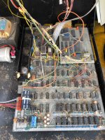
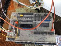
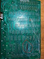
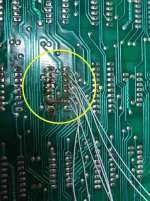
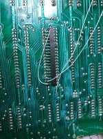
Attached there are some photos from the back side. One interesting spot is the socket G4 (yellow circle). The documentation says spare socket. The previous owner routed a some wires to the extension pins two drive the 6845 board . Does it make sense to anybody? Another spot is inside the red circle. The guy did bridge some CPU Pins with the 6522 VIA chip.

Maybe that Board is too much modified so better to trash it?:dontgeti:

Mainboard top view.jpg
Mainboard back side.jpg
G4 back side.jpg
6502_6522_Bridge.jpg
 
Well, it'll certainly be a challenge that could keep you (and some of us) busy troubleshooting for a while ;-)

I'd probably start by carefully documenting all the modifications to try to figure out why they were made and the ramifications of removing them. Interesting and probably a relatively good sign that you get some video with that 6845 board.

When referring to ICs it's a real help if you mention the location.

What test equipment do you have, if any? Oscilloscope, logic analyzer, 2532-capable EPROM burner? Do you have the schematics for that board? Should be these:
http://www.zimmers.net/anonftp/pub/cbm/schematics/computers/pet/2001N/index.html

I have some relatives in Dresden, BTW; lovely city!

Hi Mike

Oh yes, i already started to get the feeling this is a bit too much mess for me 😃
But on the other hand I do learn a lot on this project. Just bought some equipment just for this Pet including programmer (can burn also 2532!) And a logical probe. No Oscilloscope.
And yes I am reading through the 2001 schematic from zimmers.net.
So, I have some basic understanding of that stuff and I like soldering:)

Trying to understand the behavior of the logic probe. When I started to troubleshoot I tested on some data lines at the CPU, ROM and RAM. I only got Low and High. But no pulse. After replacing the faulty CPU and sockets I still get no pulse light on the probe but now I get on some pins a low AND a high and the sound is different. But still no pulse light on. I use CMOS setting.
Is this showing some life circuits or is my cheap logic probe confusing me?
 
I use CMOS setting.
Is this showing some life circuits or is my cheap logic probe confusing me?

The PET has a lot of small bipolar TTL and the 40 pin chips are NMOS. It would be better to use TTL rather than CMOS.

There should be pulsing on many signals (clock, etc) check instructions.

How is the J7 video connected to new board? So the new board is connected to the J4/J9 expansion connectors to get access to all the bus and address lines. I wonder how much of the PET 4000/8000 video logic is duplicated on the new board. Where are the video RAMS located? Are they still on the old main board? Has the character generator PROM been relocated to the new board?

You will probably need access to a scope before you can fix this system. A very interesting problem to fix. Later we may have to think about removing the new video board, and just fixing the old video circuit. The old video circuits are hard to fix which is why perhaps the original owner went to the extreme of adding a new board. Or else it was for a special purpose??
-Dave
 
As Dave says, you'll likely need an oscilloscope. It is just a fact of life. A lot can be done with a good logic probe but it is useful for the simpler error, of a stuck signal, not on a bus. The most common failure in ICs is an open pin unless we are looking at an over voltage failure, in which case it will be a short someplace. Most single failures are the open pin types. For TTL, an open pin float to a 1 if it is an input lead. NMOS parts don't always pick a direction but often float high or just become noisy. Knowing this, when analyzing the likely failing part can save some time.
As for a scope, do not buy a 1Ms scope for this use. It will constantly restrict your trouble shooting. A minimum DSO is a 15Ms to 25Ms scope. Even then, a 50Ms DSO will be better. Look for one that states the size of the frame buffer. There are features associated with the frame buffer that can be quite useful.
Another option is a logic analyzer. These are great for looking at bus related issues. These are often used most in development work as well. I tend to not use these as they require more setup time. To get a nice textbook picture of what is going on may require 10 to 15 connection. Having a pod for your specific processor is a great additional item.
I still recommend an analog scope. Many working 100MHz scopes are available at around $100 USD. I recommend getting one with a delayed sweep function as well. As you become more proficient, you'll find valuable uses for this feature.
Dwight
 
I still recommend an analog scope. Many working 100MHz scopes are available at around $100 USD. I recommend getting one with a delayed sweep function as well. As you become more proficient, you'll find valuable uses for this feature.

I totally agree. For an old 1 MHZ computer like the PET, a used analog scope of 100 MHZ bandwidth is all you need. I like the Tektronix 454 or 465 as they are fairly compact and have nice a delayed sweep function. Whatever you get, make sure it works either by a demonstration or, if buying online, at least pictures of it functioning showing both channels working with a bright trace. It should come with probes.
 
Am going to take a punt and say the graphics board most likely allows for an 80 column display on a 9 inch screen. The NEC chip looks like extra sram . If you could dump the contents of the eprom on that board for us to look at that could confirm it.
 
How is the J7 video connected to new board? So the new board is connected to the J4/J9 expansion connectors to get access to all the bus and address lines. I wonder how much of the PET 4000/8000 video logic is duplicated on the new board. Where are the video RAMS located? Are they still on the old main board? Has the character generator PROM been relocated to the new board?
-Dave

When you look on my initial post i have attached the photos how i did get the system. There is a purple/grey/white cable which connects between the 6845 board and the J7
 
Thank you guys for your value comments. I really appreciate all your help!:)
And i understand that i will need a oscilloscope. As i hesitate to present another big electronic device (beside my bunch of Retro Computers) in my home would maybe a special scope multimeter do the job?
I found a Grundig SO100 in my neighborhood for 150€ (ca. 170$), up to 100 MhZ but i believe it is already digital. But its a big beast :mad:

@dave_m: The computer obviously uses still the RAM and the Character ROM on the Mainboard because when i remove it from there i get the expected result (checkerboard pattern, white screen, etc.)

@AndyG: i will try to download the EPROM software tommorow and will post it here
 
I found a Grundig SO100 in my neighborhood for 150€ (ca. 170$), up to 100 MhZ but i believe it is already digital. But its a big beast :mad:

I found a picture of the Grundig SO100 and it looks like a nice digital scope. The vertical channel controls look conventional, but the horizontal (timebase) controls are quite different than I have seen. If that package is too big, then it may be hard for you to find a used scope that you can live with. Can you borrow a scope from a computer friend or computer club?

I am not familiar with the usefulness of the small scope multimeters.
 
The analog scope I recommend is the Hitachi V-509, because its 50 MHz bandwidth, compact, has a delay timebase and H and V sync separators built in. It also use a 10kv final anode voltage on the CRT and has a super bright sharp trace.

I agree with everything Dwight says about scopes. An analog scope with a delay timebase function is the way to go initially.

The Hitachi scopes often have the H & V sync separators built in. These are particularly handy working with vintage computers for issues with the composite video output signal. The prices are reasonable too. I just had a look on ebay, there are no V-509's at the moment but there are some nice looking V-650's that are 60MHZ bandwidth:

https://www.ebay.com/itm/HITACHI-2-...522201?hash=item23ca28ba99:g:1N0AAOSw0ThdxJKA

With the analog scope you do not have to worry about sampling issues that crop up with digital scopes and really, to be proficient with a digital scope later anyway, the analog one has to be mastered first to become familiar with issues related to triggering, appropriate timebase settings & operations, the effects of bandwidth limitations & delay timebases etc. So its hard to go wrong with these vintage Hitachi analog scopes. They are far superior to the cheap small digital scopes that have flooded the market at similar prices. For a good digital scope though you might be expected to pay well over $1000.
 
He obviously think a digital scope it better. It is different but not better, especially if you get one with a low sample rate. Like I said, look for one that specifies a large screen buffer. At least you'll get something that you won't grow out of too soon.
Most of these cheap scopes only have enough screen buffer to fill the current display. It takes away all the advantage of using a digital scope.
Dwight
 
Hi, unfortunately i have no glue about oscilloscopes (yet). Today i was looking for an older analog scope in a lower price range. Because i dont know whether i will still use it after this PET project. Therefore i hesitate to spend too much money. On the other hand i am interested in learning how to use such an equipment.

I found a Hitachi V-212 near by and it obviously also uses a trigger (whatever it is used for) and has 2 channels. Not sure whether it has H and V sync separators? I also dont know about the screen buffer size. Is this to save the screen for later view? Sorry, i really don´t know what it means and the seller also dont know.

The unit only goes up to 20 MhZ but as my interest is about retro computers (IBM, Commodore, Apple) from the 70´s and 80´s i dont worry that much.

What do you think - will this unit help me? I attached the offer and the link to the manual below.

It´s again a big box but i will probably put it in my office on the desk where i sometimes repair the controllers from my company. Maybe this baby looks a bit proffesional to my customers when they visit me for meetings :cool:

https://www.ebay-kleinanzeigen.de/s-anzeige/oszilloskop-hitachi-v-212-20-mhz-analog/1283649683-168-9559

https://mpe.berklee.edu/documents/studio/manuals/testingmet/Hitachi%20V212/V-211%20V-212%20Operation%20Manual.pdf
 
Am going to take a punt and say the graphics board most likely allows for an 80 column display on a 9 inch screen. The NEC chip looks like extra sram . If you could dump the contents of the eprom on that board for us to look at that could confirm it.

Hi Andy, please find attached the 6845 EPROM dump File. I also attached the dump from my EDIT EPROM. I´ve been told this software should contain the driver for the graphic board. Maybe someone can confirm that?

Thank you!
 

Attachments

  • add on board 6845 mostech2716.bin.zip
    902 bytes · Views: 1
  • D8 EDIT Basic 4.0 intel 2716.bin.zip
    2 KB · Views: 1
Hi,

i found an analog scope near by. Its a Hitachi V-212 with 20 Mhz and 2 channels. Unfortunately i have no glue about the screen buffer size of this unit as i am still missing the scope basics. Also the seller does not know whats about the screen buffer. Is this a kind of memory in the unit? I think i am ok with 20 Mhz as my interest is limited to Retro Computers from the 70´s and the 80´s.

I have attached the link to the Manual. Is this something i can work with?

I have also attached the Dump from the Graphic board EPROM and from the EDIT EPROM. I have been told in the EDIT ROM Software there should be the driver for the 6845 Boardf included. Can you confirm that?

I wish you a nice weekend.
Best regards
Denis

PS: I did post all this already on friday but it never showed up in the forum. It also always takes a very long time between sending a post and before being visible here - also without attachements. Is this normal?


https://mpe.berklee.edu/documents/studio/manuals/testingmet/Hitachi%20V212/V-211%20V-212%20Operation%20Manual.pdf
 

Attachments

  • add on board 6845 mostech2716.bin.zip
    902 bytes · Views: 1
  • D8 EDIT Basic 4.0 intel 2716.bin.zip
    2 KB · Views: 1
Hi,

i found an analog scope near by. Its a Hitachi V-212 with 20 Mhz and 2 channels. And it can handle an external trigger (whatever it means). Unfortunately i have no glue about the screen buffer size of this unit as I have no scope experience and knowledge at all. Also the seller does not know whats about the screen buffer. Is this a kind of memory in the unit? I think i am ok with 20 Mhz as my interest is limited to Retro Computers from the 70´s and the 80´s. Is this something i can work with?

I tried to attach the Dump files from the Graphic board EPROM and from the EDIT EPROM because I have been told in the EDIT ROM Software there should be the driver for the 6845 Board included. But my posts with the files do not show up here. I tried on friday and on saturday. I zipped both files. Maybe the forum administrator keeps rejecting this? Can you please advise how to upload these bin files?

I wish you a nice weekend.
Best regards
Denis
 
Hi,

i am doing some progress.

1) I de- installed the 6845 graphic board and dont get the black screen anymore but the same garbage screen as with the board. The reason was a bad contact to the board on the 74191, Pin 7 at G5. Therefore the CLK1 signal did not move on through the board circuit but did still go through the red wire which connected to the 6845 board. I will now try to fix the system without that board

2) I familiarized myself with the retro scope i bought last week (Hitachi V-212). Still need to learn a lot how to use it efficiently but i get used of it

3) I used 2x 40 pin sockets to prepare a NOP Generator together with my new old stock 6502 (i tested in my Apple 2 – so this CPU is definitly ok!).
Today i measured the right frequencies on all adress lines – ok!
Now i also know that my logic tester is working properly – i was quickly checking some adress lines on the RAM and ROM. There seems to be a lot of life on the messy board!:)

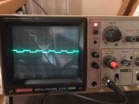
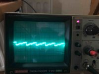
4) I am still struggling why i dont get a random garbage screen. After every power cycle it is always the same picture (see attachement). I did watch the Video from Frank when he repaired an issue on the graphic circuit and see some similarities. I have checked the input (Pin6) and the output (Pin7) of the 74LS157 (at F6) and i believe there is not a good signal on both (see attachements).
But i am not sure. I already replaced that chip but no improvement. I also replaced the other 74LS157 chips (F5, F3) but again no change. I still stuck on the same garbage picture.

Any suggestions how i should move on with my troubleshooting? Unfortunately i still do not understand how the graphic signal is routed.
I still dont know whether the non- random garbage screen is due to a faulty graphic circuit or because of something else….


Garbage without graphic board.jpg
F6_Pin6.jpg
F6_Pin7.jpg
 
Denis,
When the two video RAM chips (F7 and F8 ) are removed, you say you get a checkerboard pattern, that says that a lot of your video data path is OK. It leads me to think that something around the video RAMs is the problem. First check the sockets and the 2114 RAMs for good signals. Check that signal 'TV RAM R/W' at F8-pin 10 is high or mostly high. Did you say you already replaced the video RAM?
 
Back
Top