• Please review our updated Terms and Rules here

Commodore PET 2001 with no cursor

You're very welcome! Also in case it comes up - the PETTESTER setting on the ROMulator has PETTESTE2KV04.bin mapped to 0xE000-0xE7FF and that section is replaced as ROM. Also the kernal at 0xF000-0xFFFF is replaced with a BASIC 4 kernal, this just guarantees that the jump to PETTESTER will happen in case you have a machine with a bad kernal rom. The rest of address space is passed through so PETTESTER is actually testing mainboard RAM/ROM and not replaced versions of those, which would not be a particularly useful test.
 
Hi Dave,
I tested as in post #9 described. The 6502 SYNC is different to the identical signals at the 6520 and 6522.
Harald
Oh, I see now. The 'SYNC' signals at the VIA is actually 'Video ON' and has nothing to do with the CPU 'SYNC' signal. Just like commodore to make things confusing.
 
By the way the processor chips (all socketed) are aligned correctly in the original photo (post #1). PIA#1 and its associated logic remain the prime suspects. Dave's PETTester will really help if you can get it up and running.
Hi Alan,
You are so right, the 6520 (G8) is pointed correctly with pin 1 towards the regulators which is opposite of all the other big chips. But Harald got it correctly when he swapped 6520's.

We need Harald to set the ROMULATOR to switch setting 13, Switch 1-4 on, on, off, on. This will run PETTEST with having to program an EPROM!
 
Hi all,
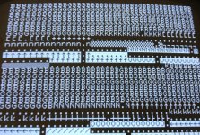
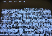
setting #13 just shows a garbage screen.
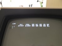
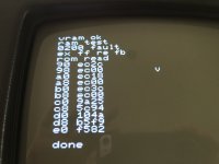
setting #14 and #15 looks more better.
should I try to connect my Raspberry Pi to the ROMulator to get more details
Harald
 

Attachments

  • setting_14.jpg
    setting_14.jpg
    1.4 MB · Views: 4
  • setting_15.jpg
    setting_15.jpg
    1.9 MB · Views: 4
sorry, next try now with my correct dip switch settings (I hope)
Harald
 

Attachments

  • setting_13.jpg
    setting_13.jpg
    1.7 MB · Views: 13
  • setting_14.jpg
    setting_14.jpg
    1.5 MB · Views: 12
  • setting_15.jpg
    setting_15.jpg
    1.9 MB · Views: 13
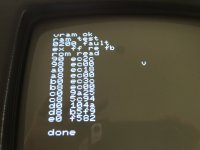
Looks like setting 14 and 15 are working. 14 is a very basic test of low RAM, and from the screen, at address 00, ff was expected and fb was read. 15 replaces the zero and stack pages and tests the rest of ram and gets rom checksums. And there we can see ram again failed right away, at address 0200. This matches what we already knew, that there was likely a ram fault. Not familiar with what we are seeing on 13 (PETTEST) but that may be a valid output, will look at the docs.
 
That is PETTESTER testing pages 0 and 1 of RAM and detecting mainly Bad memory cells and a few Good ones. It is also telling you what character was found.

Dave
 
We need to definitively find out which test is failing.

Have you installed a manual reset pushbutton?

If so, can you video a run of the PETTESTER immediately just before you press reset and post the video please.

Note that this is not the same as turning the PET ON, as we may miss the first test (or so) whilst the CRT warms up.

If you haven't fitted a reset button yet, we can talk you through it.

There are some interesting data patterns there though.

I need to go out for a walk. My brain has hit the proverbial brick wall today - I have been reviewing technical documents so I am done for the rest of today!

Dave
 
There is a utility program in the repo to get those from the ROMs, it's not documented at the moment. Next opportunity I will run that to check the checksums in question.
 
I'm very impressed with the help I'm getting on this forum. I thank you all.
I don't have a reset button at the moment but would like to add one. Where is the right point on the board (or on the ROMulator) to connect it to a button?
Harald
 
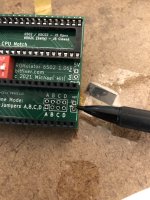
That sounds right, here is a picture of the header I was mentioning to reset the machine:
image_67159041.jpeg

connect these two points temporarily to reset the PET. You can use a pin header and jumper or just a wire, whatever you have handy.
 
That sounds right, here is a picture of the header I was mentioning to reset the machine:
View attachment 1240751

connect these two points temporarily to reset the PET. You can use a pin header and jumper or just a wire, whatever you have handy.

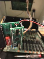
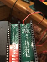
something wrong with my reset-switch? The PET does not reset
 

Attachments

  • F3000538-4B2F-4671-B129-E397C7B78519.jpeg
    F3000538-4B2F-4671-B129-E397C7B78519.jpeg
    1.2 MB · Views: 6
  • 576DA62E-C985-4742-8A1B-8D232EE5A17B.jpeg
    576DA62E-C985-4742-8A1B-8D232EE5A17B.jpeg
    1.2 MB · Views: 7
Back
Top