• Please review our updated Terms and Rules here

Commodore PET problem

prowler

Member
Joined
Aug 21, 2023
Messages
20
Location
Ontario
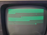
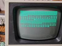
So I have a 8032 pet that isn't quite working. As you can see from the attached images I get some interesting results. I would say 75% of the time it boots up with the chirp and starts to display the commodore basic/bytes free message but then it stops. The other 25% of the time it either black screens or shows the full screen display of characters screen that the pets usually do at start.

I can confirm that the 6545, cpu, via and the UB16 PIA are all working (tested on another pet). I can also confirm that the edit rom, char rom and the first basic rom (UD6) is also working (again tested). I have tried to piggy back ram on the low ram (odd numbered chips) but that doesn't change the situation. I do not have access to a romulator and they are on indefinite back order so that kind of sucks (though if anyone has one to borrow that would be cool.)

I find it interesting that 90% of the time it does the first line correct (*** commodore basic 4.0***) and it looks like it is occasionally trying to write the next two lines as 112bytes looks like it is trying to write the memory free line and the y. looks like the end of the ready line.

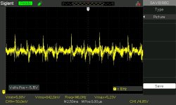
I don't know where to go from here to solve the problem. I am not entirely sure its a ram issue. I do have access to an oscilloscope.
 

Attachments

  • 20230823_233133[1].jpg
    20230823_233133[1].jpg
    3.1 MB · Views: 25
  • 20230823_151450[1].jpg
    20230823_151450[1].jpg
    4.1 MB · Views: 27
  • 20230823_151710[1].jpg
    20230823_151710[1].jpg
    2.4 MB · Views: 25
Odd question, but I know when you power cycle a PET quickly you can oftentimes get that second image before the reset timer kicks in. Is there a 555 timer on your board, and if so does that work? Since it only happens maybe 1 out of 4 or 5 times, I am not sure of a good way to test it
 
Welcome to VCFED prowler.

You will be moderated for the first 10 posts - so we will have to take the postings slowly to start with.

Item 1 - Check (using a multimeter or oscilloscope) the DC voltages on all of the voltage rails. All of the DC voltage rails should be within +/- 5% of their rated value. So, for +5V they should be within +4.75V and +5.25V. These are the maximum permissible operating values - so I would really expect them to be within the range +4.9V to +5.1V - or even closer. If you don't know where to measure, ask.

Item 2 - Check (using an oscilloscope) the AC noise on all of the DC voltage rails. If you don't know how to do this, ask.

Item 3 (as Nivag mentioned above) - Check (using a multimeter, logic probe or oscilloscope) for a good /RESET pulse on the 6502 CPU pin 40.

Item 4 - What colour are your IC sockets. A strange question - but all will be revealed shortly!

EDIT: I see you have another post stating that something is fixed. Is it this issue - or is this something else?

Dave
 
At power turn on, both the capacitors C51 and C50 have zero charge and zero voltage across their terminals. Pin 2 of the 555 is the trigger input and a low here sets the output pin 3 at a high level (close to +5V) immediately after turn on.
However, C51 starts slowly charging via R25. This 1 meg & 1uF time constant (= 1 seconds) sets how long the 555 output pin 3 is high, until the voltage on pin 6 & 7 of the 555 reaches its threshold voltage. So pin 3 is high for one second after power up. Therefore, after inversion by the 74LS04 the /RES pulse is simply low for one second after power up, resetting the CPU for one second after turn on. This allows all other voltages in the PET to have perfectly stabilized by this late time. You can think of the CPU as stuck (reset) for the first 1 second after power up, this is when the "garbage screen" can sometimes be seen on the VDU, if the VDU's heater was previously warmed up. Turning the computer on from cold, the garbage screen is not normally visible because of the time it takes the CRT in the VDU to warm up.
 
Hey daver2

item 1: The voltages appear to be generally okay. 5v rail is bang on 5v, 12v rails is 12.2v and the -5v is at -5.4.

item 2: I can't say I have measured ac ripple but zoomed in on the 5v signal at c11. Attached is what is displayed. 12v/-5v rail looks similar

item 3: reset looks normal, low than high after a second

item 4: Black. I believe I read somewhere that the white ones suck. With that said, I replaced the socket for the CPU with a much better quality one (machined pin so they are tight). The old socket wasn't making good contact. That didn't change anything though


My previous post I editted was for a different working commodore pet. I was swapping ICs from it to check some things out on this pet. I made a silly error but I got that other working commodore pet up and running again. Wish I could get this one to work too!

Hugo Holden:

I know that garbled screen can appear on fast resets but the garbled screen I get stayed on. haven't had it in a while though
 

Attachments

  • SDS00005.jpg
    SDS00005.jpg
    110.3 KB · Views: 5
Voltage readings are probably OK.

Yes, the white IC sockets 'can' suck... Hence the question...

Check to see that the CPU pin 7 (SYNC) is ticking away (a) under normal circumstances and (b) when you ge the random screen or things appear to just stop working. A permanent LOW or HIGh indicates that the CPU has gone into the weeds for some reason. Unfortunately, this can be for many reasons (ROM, RAM, etc.).

The next steps depend upon how much you want to spend and what you want to do with the machine...

You can build what is known as a NOP generator (or butcher a spare 6502 CPU to make a NOP generator). This will test out all of the address buffers and address decoding logic. Basically, you force the CPU to execute a NOP instruction ($EA) rather than what it is told to by the ROM... This will cause the CPU to cycle around all of the address space reading memory and I/O devices.

You can also download my PETTESTER. You will need to burn your own EPROM. It fits in place of the EDIT ROM (UD7). It does require a handful of instructions within the Kernel ROM (UD6) to work.

Alternatively, you can purchase one of the available ROMulator products around. The emulate ROM and RAM and some also have an in-built NOP generator and my PETTESTER. In general, you remove the 6502 CPU, plug the ROMulator into the vacated socket and plug the 6502 CPU into the ROMulator. You should then be able to diagnose most of the common faults with a PET.

Dave
Sync signal is an oscillating fine, even when the Pet is stuck.


I don't own an eprom burner and wasn't planning on getting one. I was thinking about the romulator but they are in backorder for quite some time. I might look into making a nop generator
 
Ok, so the fact that SYNC is ticking away when it is 'stuck' is actually good. Knowing this, we can see where it is stuck by looking at the pins of the SN74154 4:16 decoder.

The output pins are normally HIGH, but pulse LOW to indicate an access to one of the 16 off 4K blocks of memory.

It is simple enough to double-check the CPU SYNC pin for activity, then report all of the pins of the 74154 for HIGH, LOW or PULSE activity. I may be able to work out what it is doing from this...

Also, if you put your location within your profile, some nice PET person nearby may be able to burn you a PETTESTER EPROM for cost and a pint of beer...

Dave
 
So this will be interesting.

Sync signal sometimes stays low on boot up. Maybe 25% of the time.

When it doesn't the 74154 shows inconsistent results.


1 Oscillations
2 H (some pulsing on some boot ups for a second after beep)
3 H (some pulsing on some boot ups for a second after beep)
4H
5 Pulses (sometimes)
6 Pulses (sometimes)
7H (noticed it is high at 3.6V which seems low. For reference on my oscilloscope I show over 4V on other highs)
8H
9H
10 H
11 Pulses (sometimes)
12 L
13H
14H
15 Oscillations seen once but generally its high
16Oscillations
17Oscillations
18L
19L
20-23 Oscillations
24 H

The CPU sync does go low sometimes after about 5-10 seconds. Sometimes it doesn't go low and stays oscillating.

Sorry this couldn't be more consistent but thanks for the help so far!
Just wanted to make a correction. If it boots with a oscillating sync, it will stay oscillating
 
I think you have two (2) concurrent faults. The first is the video issue, and the second is the CPU not working issue.

We need to fix the video problem FIRST to see what is causing the crashing problem.

Are video RAMs C3 and C4 in IC sockets or not?

Can you wire a normally open pushbutton across capacitor C6. This will allow us to reset the PET without powering it off.

Can you then video the PETTESTER screen when you power the PET up. Continue to video the screen when you press (and release) the RESET button that you have added. This will allow us to look at the video screen contents before the test moves on.

Post the short video.

Dave
 
Last edited:
Sorry, please IGNORE the above post...

I posted into the wrong thread (embarrassed)...

Dave
 
Last edited:
Right, now I have remembered that your machine is an 8032 and not a 2001...

Yes, the 74154 readings are not much help. They do indicate activity on the E and F ROMs - but no activity on the screen - so pretty much what we guessed...

It is doing something, but what we don't really know...

As you say, pin 7 is a bit strange, but it is still a logic HIGH.

Dave
 
Ya it is weird.

I figured I wanted to try a different approach. I turned it on and off until I had a black screen without chirp. I figure what ever is intermittently halting the boot up sequence might be the problem. I know the cpu,via and 6545 chip are good as well as one of the PIAs (ub16), edit rom and the first (UD6) of the basic roms is okay. I am not 100% sure the order of things for this boot up sequence but I read another older post of yours I believe that leads me to believe the only other thing that might be used in the boot up is the ram. Again, I have tried piggy backing with no significant results ( though I will try again on the odd numbered low rams, maybe I will check the high rams too). I was doing some probing on the 74154 during a black screen startup and I noticed I got slightly different results.

1 Oscillations
2 H (some pulsing on some boot ups for a second after beep)
3 H (some pulsing on some boot ups for a second after beep)
4H
5 Pulses Constantly
6 H
7H (noticed it is high at 3.6V which seems low. For reference on my oscilloscope I show over 4V on other highs)
8H
9H
10 H
11 Pulses Constantly
12 L
13H
14H
15 H
16Oscillations
17Oscillations
18L
19L
20-23 Oscillations
24 H


On a successful startup i generally don't see pin 5 and 11 pulsing all the time. pin 5 is select line 4 which appears to only connect to the memory expansion slot according to the schematic but I feel it has to connect to something else. Pin 11 is select line A which is just an empty rom slot. It looks like is checking to see if anything is in the UD11 expansion slot which i figure is normal at some point during startup. I get the feeling this doesn't mean anything but I still found it interesting.
 
Yes, if there is no ROM in the 'A' socket then this doesn't make sense, unless the processor is not executing the ROM code correctly.

Pin 5 (/SEL4) is not used directly, but the CPU is accessing RAM in the range $0400 to $04FF.

RAM could be faulty, and piggy-backing only works under certain circumstances. If the output from a RAM chip is LOW and it should be HIGH, then a piggy-back RAM that works will not pull the line HIGH. You are wire-ORing two signals, and the faulty LOW will win.

This is why we need something like PETTESTER to test each sub-system one at a time - otherwise we won't get anywhere I am afraid. You are working with one hand tied behind your back and with a blindfold on!

Dave
 
Thanks for the assistance, I guess pettester or romulator is next step. For reference to one your previous replies, you cannot add location to your profile when you are a moderated user (<10 posts). Southern Ontario though if anyone reading this has a spare pettester/romulator that I could borrow!
 
That is something I wasn't aware of (not being able to add your location to your profile if under moderation). I will run this passed the mods to see if it is intentional or not...

There are a few helpful VCFEDers near Ontario I think...

Dave
 
Hello again,

I just got a romulator and installed it into this Pet. With the romulator's internal rom and ram it works! However, this doesn't fix the PET as there is clearly something faulty going on with the ram.


I tried the PETTESTER on the romulator and got the attached images. After some fluctuations at the start it settles generally on of the two attached images. Sometimes the characters flicker and change in the dotted area. . Now I am a novice but from reading your manual, it appears there is something wrong with the 0 page ram.Interestingly it shows address $7E and &FE as bad on the first screenshot. The second screenshot shows a nice consistent pattern. Not too sure how to interpret that though!

I played with the NOP generator and found that the addresses appear to be correct going into the 74ls244's (ue8,ue9,ue10). I don't know how to interpret the output of these chips though
 

Attachments

  • 20230920_170001.jpg
    20230920_170001.jpg
    3.3 MB · Views: 13
  • 20230920_201434.jpg
    20230920_201434.jpg
    3.4 MB · Views: 13
Last edited:
It does look like a RAM fault.

Have you tried to run your PET with the ROM mapped to the 'real' PET and the RAM mapped to the ROMulator?

That would clearly show a RAM fault if the machine worked OK like this.

You can simply swap the two 16K banks of RAM over, but I will have to leave that for later. I am in a rush now...

Dave
 
Last edited:
Back
Top