• Please review our updated Terms and Rules here

Compaq Portable 486/66 screen issues

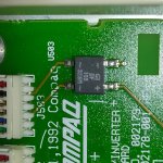
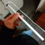
Here we go: power consumption for the Amazon bulbs is purely 6W, and it lists the incandescent equivalent as 25W. Hopefully the circuit powering the light isn't too high so I don't fry my multimeter, and so it also is compatible. How does power flow through these things? Would I be correct to assume it just flows from one end to the other? Also does anyone know if the bulbs in the 486c are DC or AC powered? I don't know if they can behave like incandescents or LEDs and take either.
 
The bulb is a miniature florescent bulb - just like the 4' overhead flickering tubes found in most older government buildings etc. Newer LCD's have LED's and have different power requirements.
 
The CCFLs backlights in laptops used to be rather high voltage, I know the one in my 486 system uses a DC-DC circuit to boost the voltage to around ~22V to drive the backlight.
 
I managed to find out the input voltage, it's 180V DC, there's an AC to DC converter looks like, but when I try to read the output voltage it doesn't read anything.
 

Attachments

  • IMG_20250118_000553_HDR.jpg
    IMG_20250118_000553_HDR.jpg
    1.3 MB · Views: 6
Sorry I meant DC to AC, there's 180v DC going into this thing, but when I try to read the voltage, it reads 0.2v AC, does anyone know what this is, and based on the output if you know it, what tubes should I get? I'm clueless when it comes to these lights, and the bulbs in it don't have any markings. All I know is that they're 10in long, and 0.5in in diameter.
 

Attachments

  • IMG_20250119_180524_HDR.jpg
    IMG_20250119_180524_HDR.jpg
    294 KB · Views: 4
I think the AC coming out wouldn't be that high, I just can't measure it accurately for some reason. The voltage probably drops from DC to AC conversion. (I don't know electronics that much so I'm just guessing).
 
That's a SMD Bridge Rectifier. It's used to convert AC to DC. You should find AC voltage between the two ~ terminals. Make sure to set your meter to the AC setting.

This part tests the same as a diode between each of it's 4 legs as that's exactly what's in it. 4 diodes wired around 4 legs 2 with the cathodes going in one direction and the other 2 cathodes reversed. With everything powered down. Set your meter to the ohms setting. You will have a low ohms with your probes in one direction, and a high reading (1K or more) when you reverse the polarity of your probes. As you work around you should get much the same readings

To have 180VDC you should have 180 to 200VAC between the two~ terminals, unless this voltage is backfeeding through some other part passing a small amount of current to this point.
 
I have other issues right now (see my other thread). I get no signal at all on my internal monitor due to problems with the graphics card. I can see half of the screen, because one TL is still working. But now, there's no signal at all because of the GPU. I have to fix that first before I can go further on this.
 
I have a compaq slt286 computer and my lcd looks the same at the first posting. Washed out with shadowing. Is that capacitors?
 
Yeah I would say so too, They usually look like that when there's bad caps, mine did the same thing, and it was a gamble whether or not it would show picture when I turned it on. I eventually cracked my screen trying to replace bulbs for it, but caps were next on the list of repairs.
 
Yeah I would say so too, They usually look like that when there's bad caps, mine did the same thing, and it was a gamble whether or not it would show picture when I turned it on. I eventually cracked my screen trying to replace bulbs for it, but caps were next on the list of repairs.
I attempted a cold cathode swap years and years ago. IT didnt go well in the reassembly unfortunately.
 
Yeah that looks like caps. If it's anything like my AST 486/33 Advantage nb there will be about 9 little SMD Electrolytics. Pretty easy to swap out with basic soldering skills. You can use tanalums. I used some small through hole eletrolyics and bent the legs to fit the solder pads. The worst is cleaning the electrolyte off the board and seperating the frame and backlight.

When the caps went on it it was dark contrast then it would flash to a complete white screen. There was also more static when it was displaying what would be colors on a color monitor

You always see some trails left on white lines on a black background. Text graphics In DOS it's really noticable. Another normal thing is a slight difference in contrast between the bottom and top halves of the screen.
 
If there's a way, I would take the controller board off and soak it in %90 isopropyl alcohol, that's what I did for my classic II motherboard to clean off the electrolyte. If there isn't a way to remove the electronics from the screen, I would just use a toothbrush, to scrub with ISO, then rinse with distilled water.
 
If thats a DSTN/STN screen , its completely normal. My Compaq looks exactly the same, although color. DSTN/STN screens always look washed out and smear like that due to how they work. They will never look like plasma or TFT screens. They just smear.
 
Back
Top