OK, this is what I have come up with.
Use RDOS to place some 'random' data into memory addresses from 0000 to 001F (say). Let's make sure there is some data in video memory to work with.
Run my test program and set the data bits D7 to D0 of port 0Fh to '00011001' (normal resolution, picture in 512 bytes). D5=0.
Test point 'T' as a trigger at the correct timebase setting (5 us/div).
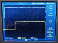
Measure and post IC46 pin 15. (/G).
Measure and post IC46 pin 1. (S).
Check (just post one of the pins as a short video) IC46 pins 3, 6, 10, 13, 2, 5, 11 and 14 for random data. IC46 inputs.
Check (just post one of the pins as a short video) IC46 pins 4, 7, 9 and 12. IC46 outputs.
If the outputs from IC46 are either permanently HIGH or permanently LOW, I would be inclined to remove IC34 and perform this test again. Don't bother to post anything other than the outcome of the test.
The outputs of IC46 drive the inputs of IC34. I want to check that the inputs of IC34 are not faulty.
Reinsert IC34 afterwards (if you removed it)...
Dave