• Please review our updated Terms and Rules here

Cromemco dazzler replica project

The same listing is on American eBay so... yeah, I guess there are 45 of these in a warehouse in Israel. That doesn't really negate the point that it's a really hard to find part. ;)
Yes, just not quite as rare as the F3342 or the TMS3417. It is quite possible that I have some of the world's remaining few specimens of these parts in my workshop. I think though there will be more of the 74HCT7731's out there, a good one to find would be the SOIC package part that were once stocked by Mouser, this more modern stock is probably about, just a matter of finding it. These would fit well on an adapter board.

It looks like the rare TMS3417 problem has "gone away", for now at least. Interestingly the TMS3417, 1979 date code, & ceramic package, is now available on ebay and plenty available by the look of it, anyone with an original Dazzler or planning to make my replica should stock up:


There was a mention, even in the 1970's that the TMS3417 was hard to get, they must have had a very limited production run. They had the vintage TI package made of very hard resin, cut off at each end with a cutting tool and pins that were perforated with a hole as the enter the IC package. I have seen that before on some if TI's early resin package IC's.

The other interesting thing about the Dazzler color encoder; they provided phase adjustments for green and red, but not blue. Blue was derived from a near exactly phase reversed burst. Because of this, the color image out of the Dazzler cannot produce a pure blue, it generates a "purplish looking blue" as there is a phase shift for the blue carrier toward magenta .You can see this looking at the still frames of the Kaleidoscope images. That is quite a "unique look" too and no doubt would have escaped the attention of the Dazzler replica output, which would likely be perfect RGB color. Again though, is that a quirk to admire or a problem to be fixed ? I'm not so sure, but I cannot help admire the way they pulled off their color encoder with a few logic gates and some L-C circuits. I've never seen that done elsewhere, generally the designer reaches for a standard color IC for composite video to do it.
 
Last edited:
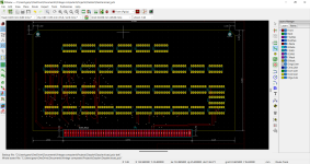
An hour or so on Kicad.

Its possible, but its going to be hard and prone to errors that might be hard to track down. I will see if I can get board 1 done without losing it :)


1665786828188.png
 
An hour or so on Kicad.

Its possible, but its going to be hard and prone to errors that might be hard to track down. I will see if I can get board 1 done without losing it :)


View attachment 1247298
Only an hour to do that , you are cooking with Gas !

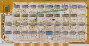
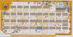
One way to eliminate or check for errors when you are done is to use my board images as a transparency and overlay it with an image of your board with a colored image of it. Then it is easier to spot if all the tracks are present and accounted for.
 
One problem, without creating a scheme, the routing and rule checks dont work, already found a track that went through a pad.
 
One problem, without creating a scheme, the routing and rule checks dont work, already found a track that went through a pad.

The schematics *are* in the manual, so if you're willing you could go ahead and reverse the whole enchilada. Being able to match the schematic to the actual board would give you a two-way check on the accuracy of both.

Having it in modern schematic form would be great if someone *did* want to do a "modernized" reproduction that, say, improved the "digital" half (updating the memory addressing circuitry) but kept the same pixel/color generation chain...
Apparently, so I have read, the first generation supposed "replicas of the Apple 1 pcb" were done from a schematic capture methodology. But the routing and track configurations didn't match the original and some folks didn't like that. So later generation ones were better made for the tracks to match exactly or very close to the Apple 1 board.

I don't know how George at LD electronics converts my files in Altium Designer, but he acquires an exact match of the tracks I have drawn, which match the original board in their configurations. So the oddball method does result in an exact or near exact clone of the original manufacturer's pcb.

Altium I think was an evolution from the Protel pcb drawing program popular in Australasia, but, I have never used it myself. I was thinking of making a perfect replica of the Apple 1 pcb that would be hard to distinguish from the original, but I have not got around to it yet.

I found the Dazzler schematic very helpful for checking for errors on the final design, because the Cromemco images of the foils were so poor that in places some were very difficult to make out. That took me a lot of time.

At the moment I'm sort of doing a replica project in reverse, no schematic or manual available, so what I have done is reverse engineered the pcb foils first and I'm acquiring the schematic from those diagrams, it is quite a long job with a 28 IC circuit. It is much easier to draw out a schematic if you have designed the circuit yourself, but there are 101 ways to draw out somebody else's schematic. Ideally the flow of it should be done to help the circuit analysis.
 
The other thing is that the sync generator doesn't include equalizing pulses around the vertical sync, so there is a small interlace (line pairing error) which you could regard as a "defect" or "adding to the charm".

Mildly amusing, maybe. While the pot roast was cooking this late afternoon I decided to see if I could wrangle interlaced video out of the software-CTRC thing I'm using as the main moving part for my "universal" retro video card project. Every... single... piece... of Atmega8 video sync generation code I could find does progressive scan, including the skeleton I started with, so... I settled down with a manual from 1988 to see if I could make the needful come out of the chip timers all by my own dumb self.

Good news, I guess, is I succeeded, but bad news is I also have a little bit of line pairing/clustering/whatever. Curious what the deal is because I did implement equalizing pulses; It seemed like I couldn't convince my monitor to interlace without at least a token attempt at them. Unfortunately I think if I really want to see deep enough to find out the root cause I'm going to have to give in and cough up the money for a digital 'scope, I can't convince the old tektronix to show me a clear enough picture of the whole refresh period.

Anyway, so maybe there's more to it than just the equalizing pulses. In my case I suspect it's a slight uneven-ness in the pulse spacing that results from having to reprogram the timer on the fly to count half-lines instead of full lines inside the vertical sync area. Whatever, I'm calling it good enough for now. :p

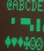
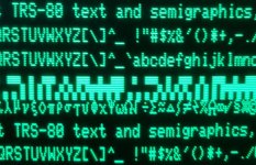
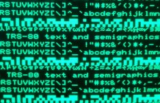
(The "pairing" is most obvious on the graphics characters. This is just a "double-scanned" version of what was the progressive scan's 262-line display, next step is to render some stuff that actually uses the interlace. Including maybe an emulation of the Dazzler's high-res monochrome mode, which effectively requires 384 lines interlaced to do right...)


interlaced_text.jpg
 
Anyway, so maybe there's more to it than just the equalizing pulses. In my case I suspect it's a slight uneven-ness in the pulse spacing that results from having to reprogram the timer on the fly to count half-lines instead of full lines inside the vertical sync area. Whatever, I'm calling it good enough for now. :p

It is interesting that in the UK system of 405 line TV, no equalizing pulses were used even in the late 1950's, but RCA were using them basically the whole time and the need for them is discussed in various pre-WW2 American TV technical publications, typically by Fink and post war by Grob.

Practically all TV's and VDU's after about 1960 were expecting to see equalizing pulses in the composite video signal in all countries.

Many of the early computer and video game boards put out a non interlaced signal (like arcade Pong 1972) but after a while the computer industry and video game industry moved to proper interlaced scan syncs for composite signals at least, complete with the required equalizing pulses. By 1974 Atari had moved to an interlaced scan in their Tank Arcade game.

However the benefit of RGB style signals was inescapable for computer graphics & games and eliminated the problems of chroma carrier interference with the higher range luminance signals. In many ways the World only ended up with the compromise of composite color video because it had to be compatible with the vintage monochrome signal on the millions of B&W TV sets already running in peoples homes, at the time the transmissions shifted to color.

If there are no equalizing pulses the VDU (or TV) can be tweaked to an extent to help ameliorate the line pairing. Many of the 1950's vintage UK TV's used an "interlace diode" for this purpose (you won't read about these in the American TV literature because they didn't need them).

One classic UK made TV, which has an iconic look to it, used this method, the Bush TV-22. Because of the look of this set they have turned up in a number of movie period pieces as props.
The interlace problem for them is discussed on page 25 of this article I wrote about the set:

www.worldphaco.com/uploads/BUSH_TV22.pdf
 
Many of the early computer and video game boards put out a non interlaced signal (like arcade Pong 1972) but after a while the computer industry and video game industry moved to proper interlaced scan syncs for composite signals at least, complete with the required equalizing pulses.

In the consumer realm progressive “NTSC” was common into the 1990’s. It made sense for computer applications at least because the flicker you get on standard monitors if you have individual finely-defined dots refreshed at only 30 Hz is absolute murder. (Granted it seems like it bothers some people more than others.) Not sure why it stuck around so long in video game consoles, especially after the video outputs for those started coming from monolithic ASICs where presumably integrating it wouldn’t have been much trouble, but maybe the anti-flicker argument still held some weight.

Anyway, I’m interested to see if interlace actually buys me any useful functionality. Also need to see what modern LCDs and composite adapters think of it.
 
It looks as if its going to be possible, but it will take a long time. Tried

Im just using Kicads default trace width for most apart from the obviously thick ones, not sure if thats any problem for this application.

Dont hold your breath

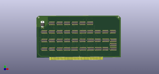
Dazzler.png
 
Anyway, I’m interested to see if interlace actually buys me any useful functionality. Also need to see what modern LCDs and composite adapters think of it.
Interlace gives double the number of visible scan lines, so it effectively doubles the vertical resolution. But "perfect interlace" afforded by equalizing pulses is more of a luxury. Though post the 1980's practically every composite sync generator chip included these pulses.

I just looked at the interlaced sync generator in the Atari Tank, from 1974, I have all the technical data, it was done with 74 logic chips & 74161 counters. As far as I can see there are no equalizing pulses, but they did a good job on the half line difference per field, nice circuit.

Also, there is this interesting paragraph, in their technical manual of the game, this is at the near dawn of the video gaming industry (attached). It is quite a remark to find in a technical manual full of schematics and probably belongs in a behavioral science book.
 

Attachments

  • TANK.jpg
    TANK.jpg
    82.5 KB · Views: 11
Interlace gives double the number of visible scan lines, so it effectively doubles the vertical resolution.

Of course, yeah. I’m just worried about practical concerns like “will the flickering burn my eyes too much to actually use it”. I also need to do some compatibility testing to make sure it’s actually working on other monitors, that it’s interlacing on my Tandy VM-4 isn’t just a lucky fluke. Really interested to see what my LCD TV and HDMI adapters think of it.

(Haven’t gotten to that yet because I’m neck deep in rejiggering the address generation to work in Interlaced. Have linear framebuffers displaying correctly, still a few bugs lurking in character/tile mode. Pretty sure I know the problem, too tired to fix it until tomorrow.)
 
It looks as if its going to be possible, but it will take a long time. Tried

Im just using Kicads default trace width for most apart from the obviously thick ones, not sure if thats any problem for this application.

Dont hold your breath

View attachment 1247318
Gary,

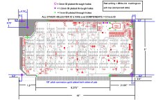
Also, don't forget that when you actually order the pcb , you need to be very specific about the hole diameters.

If you miss that then you will not be able to fit various parts.

For the most part I chose 0.7mm dia holes for the IC socket pins, and the vias. This is unusual as a lot of modern pcb programs specify the default vias as so small you need a microscope to see them. Old school vias were much larger and much more robust.

Also, for example, the ceramic variable capacitor requires 1.2 mm dia holes. You would not know this unless you had one of these original capacitors in front of you on your desk (as I did).

If you get a board back from the makers and you cannot fit the components, it is not a good feeling.

To help you here, I have attached the sheet I used to specify the holes, that I sent to LD electronics.

As you are now finding out for yourself (which is by far the better way to learn things by falling into a pothole, or not) the task of making these boards was not entirely easy or simple.

But, if you stick with it, from the way you are going, I think you can do just as well too, creating Gerbers that all can use.

And, of course, then there are the white ink markings.
 

Attachments

  • BOARD1DIMINKj.jpg
    BOARD1DIMINKj.jpg
    1.2 MB · Views: 18
Last edited:
The via info is really useful, thanks.

Trouble is with Kicad, it doesn't like the more 'freeform' tracks so I am not trying to make an entirely accurate replica, just something that works at first if possible.
 
The via info is really useful, thanks.

Trouble is with Kicad, it doesn't like the more 'freeform' tracks so I am not trying to make an entirely accurate replica, just something that works at first if possible.
Gary,

You are more than welcome.

To help you further with "The Devil is in the detail" problem and support your hard work, I have attached some more images.

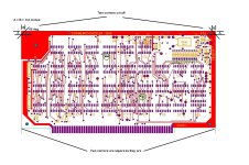
One of them shows how the pcb corners near the rear of the boards were tapered off.

Note the error in the white writing for IC 12 saying 7393 instead of 7493 on the previous images.

Silicon Chip magazine in Australia took a liking to my Dazzler reproduction and published a very large article on it, in their September 2021 edition. Their Engineers re-drew my board overlay diagrams to make them look better for a magazine printed article (scan from article attached).

Also, on my Dazzler boards the capacitors, C40 and C41, 10uF 25V types, I used mil spec axial Tantalum caps, rather than axial electrolytics as my preference for the build. These are readily available.

These additional images might also help you in your current quest, which I am very familiar with, every track you go down, I have been there too and it is a long and winding road. (I'll stop there before I quote another song)
 

Attachments

  • DAZ2.jpg
    DAZ2.jpg
    1,007.1 KB · Views: 16
  • DAZ11.jpg
    DAZ11.jpg
    1 MB · Views: 16
  • board1info.jpg
    board1info.jpg
    514.7 KB · Views: 15
Last edited:
I have made a bit more progress on the library.

I wrote part of the code once, then looked at it a couple of days later, thought "which idiot write this" and simplified it further.

I am quite pleased with the result so far - but I may not be tomorrow when I have another look at it!

The comments are a bit terse though. They are adequate for me at the moment, and will be fine for a couple of weeks whilst at the development stage, but I will start to improve them once I do a bit more debugging and the code is actually doing what I want it to do.

I have added some macros to 'hide' some of the underlying complexity. For example, aligning the memory buffer to a 512-byte boundary in memory and configuring the address for the I/O port.

Dave
 
I just looked at the interlaced sync generator in the Atari Tank, from 1974, I have all the technical data, it was done with 74 logic chips & 74161 counters. As far as I can see there are no equalizing pulses, but they did a good job on the half line difference per field, nice circuit.

I wonder how these old circuits play with digital televisions. Asking, because, well...

Made a bunch of progress on my circuit, I've beat it into submission so it's doing both linear framebuffers and character modes correctly, and it can even switch on the fly between interlaced and progressive modes. Running some tests it looks good and stable on the old CRT in both modes:

Progressive:

progressive_text.jpg

Interlaced:

Interlaced_text.jpg

My luck trying it on LCD display devices has been... pretty mixed, though. The $10 composite to HDMI adapter I use for experimentation time because it's been mostly reliable with progressive scan video has this interesting habit of randomly deciding to flip the line order on the interlaced content after mode switches. (Resulting in a gross sawtoothed mess.) Yanking the RCA plug out and sticking it back in will usually fix it. On the other hand, the dirt cheap 8" LCD TV I usually don't test with directly because its composite input is terrible with progressive input (it often won't lock onto my TRS-80 at all) seems fine with it. (But it's hard to really get a lot out of that because its screen quality is so low.) A Composite to VGA adapter I also had kicking around doesn't see anything, stays on a blue screen, but that I kind of expected, it seems to hate every monochrome output I've ever thrown at it. (Maybe it needs to see a color signal to wake up.)

So... to get to the much belabored question, out of curiosity, do you have any experience trying to use the real Dazzler with a digital TV? Does it behave "nicely" or is it kind of hit and miss?

(FWIW, I do think there might be some additional complicating factors going on. My video termination is a crude mess made solely of resistors tying together the shift register output and sync lines, maybe there is a decent chance matters might improve if I built a real proper output stage. At the very least an output transistor and better termination?)
 
Last edited:
I wonder how these old circuits play with digital televisions. Asking, because, well...


So... to get to the much belabored question, out of curiosity, do you have any experience trying to use the real Dazzler with a digital TV? Does it behave "nicely" or is it kind of hit and miss?

(FWIW, I do think there might be some additional complicating factors going on. My video termination is a crude mess made solely of resistors tying together the shift register output and sync lines, maybe there is a decent chance matters might improve if I built a real proper output stage. At the very least an output transistor and better termination?)
It is a good question. I wish I could answer it.

I have heard of difficulties applying less than perfectly standard composite video signals to digital TV's and VDU's and some won't tolerate them.

But, I have little experience with this because I generally use real vintage CRT VDU's (because I'm obsessed with CRT's) and have very few if any digital based screens with composite video inputs. I have never tried a Dazzler output on anything other than a CRT VDU.

There are at least five things with the Dazzler video output that are "non standard" but my CRT VDU did not protest. This is just what I noticed off hand:

1) the H scan frequency was a little of standard NTSC
2) the burst pulse is wider than normal with more cycles
3) the burst pulse appears right through vertical flyback and vertical sync time, it was not gated out.
4) There are no equalizing pulses we talked about.
5) the blue color phase is not "True Blue"

The color decoders in CRT TV's will lock to the burst regardless of some oddities as long as the frequency is close and the rest of the sync & scan circuits are "very forgiving" for "less than standard timing". But whether some type of digital display might be this forgiving, I am not sure.

Remember Macrovision anti copy pulses added into the VHS composite signal ? Gigantic alternating disturbances in the vertical blanking interval. The CRT TV or VDU had no complaints, it was only the VHS recorder that got fouled up, so if you tried to dub a tape it was a disaster, but no problems watching the original tape. That is a testament as to how tolerant CRT CDU's are of less than normal signals. Though vintage CRT TV sets from the 1950's that did not have very good retrace blanking can get display issues from the Macrovision pulses.
 
Last edited:
Back
Top