• Please review our updated Terms and Rules here

Help with Sergey's 8-Bit FDC and Serial Port board.

Hi, Sergey. I had posted details on the Monster FDC GitHub issues, but in short I'm using an SST PH29EE010 EEPROM. The system is an IBM / Alaris 'Leopard' 486SLC2 running at 50Mhz. I believe BIOS shadowing is turned on, but I didn't think that affected peripheral ROMs - unless the OpenDOS memory manager is deciding to remap them (?).
Well, OpenDOS memory manager does not run until you boot the machine, and the fact that it proceeds past identifying the Flash ROM, means that the setup utility can write to the ROM (and likely it is not shadowed)
Now 486/50 MHz is much faster than the systems I've been using in my test/development. The flash code uses simple delay loop, so on such fast machine, it is likely that the delay is too small, and it times out before the Flash ROM block is erased.
You can try increasing the AL value at flash.inc:225

xor cx,cx

.write_erase_byte1:
mov al,20h ; additional delay
; Am29F010 is slow to erase...


I need to fix that code to use CPU speed independent delays, such as using port 61h refresh flag
 
I need to figure out why MF BIOS cannot save changes back to the EEPROM. With version 2.6 it corrupts something and the splash screen disappears - need to reflash with xiflash to get it back. With version 2.2 it complains that it's unable to write to the EEPROM and displays a block of configuration data. Why is xiflash able to write, yet the built in 'W' function cannot?

Ack - crossed in the wires with Sergey's answer. I'll give that code change a try.
 
The Multi-Floppy BIOS is pretty much work in progress... Let me know if there is a way to make it easier for RAYXTFDC to detect it
Having the "Multi-Floppy BIOS, version x.xx" string at a consistent offset would be good. Like right after the jump instruction that follows 55 AA.

(BTW, this is pretty much the first time I hear about it, and if I Google it, it only finds this forum thread)
With good reason.

Background:

Over many years, we have diagnosed many issues in relation to the XTIDE Universal BIOS (XUB) sitting in an XT-IDE/XF-CF card.
Issues like:
- Bad XT-IDE/XF-CF card, resulting in the ROM not appearing at all in memory space.
- Bad XT-IDE/XF-CF card, resulting in the ROM appearing at an address that differs to what the card's switches/jumpers are set for.
- ROM appearing at an undesired address because user has set switches/jumpers incorrectly.
- Users not reporting the "D000 ROM" (or variation of) appearing on-screen because understandably, they didn't realise that "D000 ROM" is an error.
- Attempted use of the XUB on a computer that does not support BIOS expansion ROM's.
- Strange symptoms, that turned out to be because the XUB was appearing multiple times in memory space. (The ROM size switches/jumpers being the usual cause.)
- AT version of the XUB running on a PC or XT class computer.
Etc.

Over a year ago, I wrote RAYXTIDE to pick up such situations. A run by the user quickly rules out various problem causes for us.

So, a couple of days ago, with fjk61011 in this thread reporting possible ROM related issues in a 'Multi-Floppy BIOS' fitted card, I thought, why not modify RAYXTIDE to become RAYXTFDC !
A possible enhancement might be to report the contents of the main status register of both primary and secondary controllers.
 
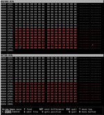
Hi, Sergey. I doubled the erase timeout and tried writing configuration again from the F2 menu. This time I grabbed dumps of the eeprom before and after. As you can see from this screen shot, the write operation is clobbering the configuration area. Any suggestion as to what I might try next?

eeprom_diff.png
 
With version 2.2 it complains that it's unable to write to the EEPROM and displays a block of configuration data. Why is xiflash able to write, yet the built in 'W' function cannot?
From what I see in the release notes at [here], "128 KiB Flash ROMs" (e.g. your PH29EE010) were not supported until version 2.3
 
Having the "Multi-Floppy BIOS, version x.xx" string at a consistent offset would be good. Like right after the jump instruction that follows 55 AA.

You've got it! I updated the BIOS code and moved the messages to the beginning of the ROM, so that now Multi-Floppy BIOS string appears in the beginning at offset 6, note that it is prepended with CR-LF characters:

00000000 55 aa 10 e9 71 08 0d 0a 4d 75 6c 74 69 2d 46 6c |U...q...Multi-Fl|
00000010 6f 70 70 79 20 42 49 4f 53 2c 20 56 65 72 73 69 |oppy BIOS, Versi|
00000020 6f 6e 20 32 2e 37 61 2e 20 43 6f 70 79 72 69 67 |on 2.7a. Copyrig|
00000030 68 74 20 28 43 29 20 32 30 31 30 20 2d 20 32 30 |ht (C) 2010 - 20|
00000040 32 32 20 53 65 72 67 65 79 20 4b 69 73 65 6c 65 |22 Sergey Kisele|
00000050 76 0d 0a 44 69 73 74 72 69 62 75 74 65 64 20 75 |v..Distributed u|
00000060 6e 64 65 72 20 74 68 65 20 74 65 72 6d 73 20 6f |nder the terms o|
00000070 66 20 74 68 65 20 47 4e 55 20 47 65 6e 65 72 61 |f the GNU Genera|
00000080 6c 20 50 75 62 6c 69 63 20 4c 69 63 65 6e 73 65 |l Public License|
00000090 0d 0a 0d 0a 00


I'll try to fix Flash ROM the issue that shirsch is reporting. I suspect it is related to his system being too fast, so ideally I'd like to fix it by using the AT-style delays on AT systems.
Over a year ago, I wrote RAYXTIDE to pick up such situations. A run by the user quickly rules out various problem causes for us.

So, a couple of days ago, with fjk61011 in this thread reporting possible ROM related issues in a 'Multi-Floppy BIOS' fitted card, I thought, why not modify RAYXTIDE to become RAYXTFDC !
A possible enhancement might be to report the contents of the main status register of both primary and secondary controllers.

I would like to appreciate your support for XT-IDE and FDC controllers. Let me know if I can be of an assistance - at least on the technical side of the things, such as improving the BIOS extension code and documentation.
 
You've got it! I updated the BIOS code and moved the messages to the beginning of the ROM, so that now Multi-Floppy BIOS string appears in the beginning at offset 6, note that it is prepended with CR-LF characters:
Thanks. That helps.

I would like to appreciate your support for XT-IDE and FDC controllers. Let me know if I can be of an assistance - at least on the technical side of the things, such as improving the BIOS extension code and documentation.
Will do.

And thank you for your great support of the vintage computer hobby (obsession?)
 
From what I see in the release notes at [here], "128 KiB Flash ROMs" (e.g. your PH29EE010) were not supported until version 2.3
That is correct, which is why I tried this with 2.6. Version 2.2 complains immediately and doesn't try to write.

Thanks for looking into the issue where the BIOS write is clobbering the configuration data. I looked at the code and noticed a distinct code path for PH29EE010 devices. Have you tested against that part number in your setup? Your thoughts about system speed are probably spot-on.
 
Hi, Sergey. I doubled the erase timeout and tried writing configuration again from the F2 menu. This time I grabbed dumps of the eeprom before and after. As you can see from this screen shot, the write operation is clobbering the configuration area. Any suggestion as to what I might try next?
Please try using the latest Multi-Floppy BIOS ROM version available (2.6)
If that still doesn't work, try increasing the timeout even further... set AL to 0FFh...

Once I have a couple of hours available (likely later this week, or sometime next week), I'll work on implement CPU-speed independent flash code, similar to that of xiflash.
 
You have an XT-IDE card. If you have a serial port on your IBM XT (or XT clone), and have certain other hardware, then consider the use of a serial drive - see [here].
My null modem cable has arrived as well as my USB to com adapter. Whilst waiting for those I discovered my windows pc has a serial port header and I have a serial cable an bracket to bring cable from motherboard to outside of the case
 
Please try using the latest Multi-Floppy BIOS ROM version available (2.6)
If that still doesn't work, try increasing the timeout even further... set AL to 0FFh...

Once I have a couple of hours available (likely later this week, or sometime next week), I'll work on implement CPU-speed independent flash code, similar to that of xiflash.
I was using version 2.6. Easy enough to try a longer timeout. Will let you know if that works out.

UPDATE: Just tried with 0FFh. Same results. It clobbered the configuration area.

Also, bear in mind that xiflash is not able to detect an unprogrammed PH29EE010. I reported this in an issue on the Monster FDC GitHub project. Once I boot strapped the setup by writing in a programmer, xiflash was able to see it and (re)flash properly from that point on. Tried a couple of different chips with the same result. So even in xiflash there's something going wrong.
 
Last edited:
I was using version 2.6. Easy enough to try a longer timeout. Will let you know if that works out.

UPDATE: Just tried with 0FFh. Same results. It clobbered the configuration area.
Thanks for trying. I already modified the flash.inc to use PIT delays that are independent of the CPU speed. I'll do some tests on my side, hopefully in the next few days, and I'll update the code in the GitHub.
Of course, if you like, I can provide you the code and the binary, if you like to help with testing.
Also, bear in mind that xiflash is not able to detect an unprogrammed PH29EE010. I reported this in an issue on the Monster FDC GitHub project. Once I boot strapped the setup by writing in a programmer, xiflash was able to see it and (re)flash properly from that point on. Tried a couple of different chips with the same result. So even in xiflash there's something going wrong.
I have a theory about this observation. Apparently 29EE010 ships with the Software Data Protection (SDP) disabled. Therefore, it is possible that instead of entering the Software ID mode, it just starts writing the commands into the flash memory, as if they were data. Programming the Flash ROM enables SDP, so the Software ID mode works normally after that. If you still have an unprogrammed chip, we can test this theory.
You can do the following:
  1. Use DEBUG to check the locations 0x2AAA and 0x5555 in the chip (using "D E000:2AAA" and "D E000:5555") commands. On an unprogrammed Flash ROM, they should contain 0xFF
  2. Try running xiflash on the new chip
  3. Use DEBUG again to check the locations 0x2AAA and 0x5555 in the chip (using "D E000:2AAA" and "D E000:5555") commands. Now, I expect to see the Software ID commands written as data. That would be 0x55 for address 0x2AAA and either 0xAA or 0x80 for address 0x5555
If that's what you observe, I can either add an SDP enable sequence to the xiflash as a separate function, or check feasibility of using that if Software ID fails (and then retrying Software ID)
 
I don't understand the following:

As stated before, when the XUB discovers a serial drive, it will end up being mapped by DOS to a drive letter, e.g. A:, B:, C:, D:, ...
The following table will give you an idea of what drive letter may be used by DOS if a drive in the computer is booted from.

IMPORTANT: Here, we are not booting from the serial drive. Booting is different; things can change. See the following booting section.

Type of serial driveExisting hardware in vintage computerSerial drive ends up mapped as:
floppy/disketteMotherboard is configured for zero floppy drives. See note 1.Drive A: if booting from C:
floppy/disketteMotherboard is configured for one floppy drive.Drive B: if booting from A: or C:
floppy/disketteMotherboard is configured for two floppy drives.See note 6
hard driveThere is no existing hard drive (includes CF, DOM, etc.)Drive C: if booting from A:
hard driveThere is one existing hard drive (includes CF, DOM, etc.)Drive D: if booting from A: or C:
 
Last edited:
The client detects the my_720k.ima ...
Good. And to note is that MY_720K.IMA is an image of the floppy/diskette type.

I don't understand the following:
So putting booting from the serial drive aside for now.

You are booting to DOS on your computer, and I am going to assume that it's from the DOM attached to your XT-IDE card. You have a C: prompt, which is the DOM.
What you should discover now is that:
* If the XT or XT clone is configured for one floppy drive (logical A: ), that you now have a B: drive, which is the serial drive.
* If the XT or XT clone is configured for two floppy drives (logical A: and B: ), that per note 6, you may need to do some searching to find what drive letter has been assigned to the serial drive.

The XT-FDC may 'complicate' the situation, and so for now, I suggest that you remove it whilst you are 'learning' about serial drives.
 
Back
Top