• Please review our updated Terms and Rules here

Homebrew TVT I picked up

I was just thinking, you may want to follow A5 from the RAM since the counter may be a 4 bit counter rather than more. A0 to A3 would be on the same counter while A4 to A5 would be on the next counter.
A5 comes from the RAM pin2 and goes to pin 12 of the left '157. The same rule applies for pin 13 and 14.
Dwight.
 
Does the fact that A0 goes to that BCB IC change your thinking? Also pin A9 goes to a 74ls00 rather than one of the 157s. I can't find anything on Google that explains what that BCB IC is. I think it is a generic replacement for a 74xx but I cannot find a reference on Google. I'm thinking A0 and A9 being separated from the others has some significance.
 
I was looking at your boards some more. The EPROM on the Archer board looks like it is to send a string of text to the video board ( possibly a goffy power on reset?? ). The board has some counters on it and feeds to the TVT board. The UART goes through the bottom EPROM and then to this extra board before going to the TVT board. There looks to be some '157s there that would select the source ( my guess ). The two with the UART look to be translators, as I said ( maybe for parity but could still be something else ).
If it is to be a reset, it would send a line of spaces and then a return for each line. That kind of makes sense as the TVT may not have had the circuit designed to clear the screen although it could be. The layout makes sense then.
I suspect the other weird part are all 7430's ( look at the ones with the pained numbers ).
Dwight
 
Does the fact that A0 goes to that BCB IC change your thinking? Also pin A9 goes to a 74ls00 rather than one of the 157s. I can't find anything on Google that explains what that BCB IC is. I think it is a generic replacement for a 74xx but I cannot find a reference on Google. I'm thinking A0 and A9 being separated from the others has some significance.

I'm thinking, it may have just been that he was running out of '157s. Three gates of a 74LS00 makes another mux. It may be that he needed a 3 input mux but I can't imagine what for. It may be that he scramble the addresses to the RAMs. That would be bad because you'd need a scope to see which addresses were which. The highest frequency on would be the logical A0 and the slowest the A9, when the video is running.
I'll be off the air for a few hours.
Dwight
 
Here's what I find puzzling. You said grounding pin 12 "DATA OUT" of each 2102 changes characters on the screen, but not immediately.

That doesn't make sense. It shouldn't take any longer than 1/30 of a second for all the characters to change. Not to the same character, but just to change in some way.
 
Ok. I don't know if you read earlier, but A0 doesn't seem to have any sort of clock signal, etcetera. I suppose maybe one of the inputs to the 74ls00 is broken. Will have to investigate that. But I'm concerned it may be on purpose.
 
Here's what I find puzzling. You said grounding pin 12 "DATA OUT" of each 2102 changes characters on the screen, but not immediately.

That doesn't make sense. It shouldn't take any longer than 1/30 of a second for all the characters to change. Not to the same character, but just to change in some way.

Sorry maybe I worded that badly. What I mean is, if I ground pin 12 on one of the 2102s, *most* characters onscreen will change, but some don't. Same with if I move to the next 2102 and so on. The way I read your instruction, if I grounded pin 12 on one 2102 all characters on screen would change in some way.
 
Count "most". 7/8? 3/4? ½? An actual count will be very helpful in determining how the RAM is arranged. That is, what's the row and column number of the first and last character to change? Are they all consecutive?
Pictures are worth thousands of words.
 
Okay, here's the link to the folder again. I took a pic without any 2102 pin 12s grounded, then a pic as I grounded pin 12 on each one.

https://drive.google.com/drive/folders/1rf7FAdmtQD1nhOnoEbiij-juC7CpdmOt?usp=sharing

It's hard to tell with such a jumble.. but now that I'm trying it again it does kind of look like they're all changing. I'm certain they weren't before though. Before it would change about 80% of the screen, but there'd be these stubborn characters that would not leave.
 
Breaking news.

I have solved the repeating column problem. I was curious why there was no signal for A9. So I traced it back from pin 14 on the 2102s to pin 6 of the 74LS00. As noticed previously, pin 6 had no signal, just a low tone on my probe. So I looked at a 74LS00 diagram. Pin 6 is the output of a NAND gate. I followed the inputs for that NAND gate (pins 4 and 5) and discovered that pin 5 was tied to pin 8, which is the output of another NAND gate. I then checked the inputs of that NAND gate, pins 9 and 10. 10 was low, 9 had a clock signal. But 8 was low. According to the truth table, this could not be - if one input to the NAND is 0 and the other is 1 (which the clock signal would be), then the output of 8 must be 1. So I should be seeing a clock signal on pin 8. Since this is all within the chip itself, it means either something really weird is going on, or the chip has failed. I swapped in another 74LS00.. boom.. mirror column gone! The irony is, this 74LS00 was one I'd swapped from my spares. It was fairly new. Drat.

Anyway, that solved that. I was able to, using my two-key method, type spaces all the way across, one at a time without having two cursors or two characters being deleted at once. So that's good. However, when I hooked up the 6800 and ran my punch command, although it was no longer spilling out into the second column, it was still doing this:

https://youtu.be/s6AH6tfUUk0

In the video, you can barely see the 'prompt' appearing when I power on the SWTPC. I then give it the (P)unch command, and you can see various characters being produced on the left side as it tries to punch out S records. Near the end of the video, I do a reset on the 6800, and do a (M) emory examine command at address 0000 and then just start entering double zeros. It seems to get one of them right. But most else is wrong. Since I so far can seem to type okay, I'm tempted to think my issue now is with that UART board and/or maybe the EPROM.
 
ops I was typing and sneezing and didn't see the last post get there.
I don't expect much fro the 6800. We still have no idea what the EPROMs decode. Just keep it in loop back so we are all apple, without orange, and avacados. We can fix a few other things first.
Dwight
Dwight
 
Last edited:
It goes down to the next line.

But.. I can see a second cursor shadowing the first. I didn't count how far back the second cursor is but it's consistent. And while I can type a line of something I want, it is changing things several lines down randomly. It's weird.. I can type T and Y back and forth and get a complete line of those, but other key combos don't seem to do anything, even though I can see strobe being triggered. Or for example I can type Q and I repeatedly and it will produce a Q, but not an I, and the Q only will appear if I type I first. This is with the 6800 'removed' and just the TVT looping back to itself, btw.

I don't think the EPROMs you have are all correct. That would cause funny things on the letters not matching. It is relatively clear that they don't match you 6800 machine either. If that continues to bother you, you can bypass the EPROMs as I think there are some errors in them anyway. You can get some 24 machine pin sockets and just run the address to the data pins, lowest to lowest and highest to highest for the 8 bits. Mark the two EPROMs so that they can be explored later so you know which sockets they come from. We don't know what they were up to anyway and I'm not at all surprised that they are not working with your 6800 machine.
With your fix of the column issue by tracing A9 of the RAMs, it would indicate that the builder didn't keep the address lines straight. That may make other issues harder to trace later. If he'd keep them straight, it would have been A4. The fact that he didn't use the '157s for all the muxs is also a pain.
Lets see if we can deal with the multiple cursors first and get the screen working right. You can also make a couple EPROM bypass connectors, as I don't fully trust them anyway at this point. It will make it easier to analyse character issues that seem to worry you anyway.
By tracing the address lines back through the muxes, we should be able to determine which counters are used to keep track of the video position and which are used for the character entry counters. From that we should be able to figure out the multiple cursor problem.
So, two to does. Make some EPROM bypass sockets for the two EPROMs next to the UART and find the counters for the two different functions. The counters are the keys to how the entire video and key entry work. We still don't know what the other EPROM on the archer board does. I'm still thinking it is for a reset, as we've not seen a screen clear function yet. As long as it isn't interfering with normal text entry, we can hold off on figuring it out till later.
One wonders how he did the cursor. He'd have to look for a match between the two counters. He could have used a pile of gates ( he used a number of 7430s ) or some address comparitor chips. That is why it is important to track down the two counters!
Dwight
 
Darn 15 minute thing!!
Anyway, I want to say, you can directly jumper on the sockets. You can use 28 ga wire. That is the same size as used on those white prototyping blocks. If you've been using those, you should be able to come up with 16 wires.
Dwight
 
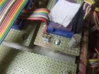
I don't know if this is relevant, but I was looking at the first EPROM board (the one the keyboard plugs into, and noticed three little 'plugs' you could put a jumper wire into:

20190701_091716.jpg

I traced them. One has -8V on it and connects to the VGG pin of the 1702. Another connects to keyboard ground. And the final appears to connect what I've assumed is the strobe. It was a wire that had broken off at some point in the past from the keyboard connector. I could find only one pin on it that looked like wire had broken loose, and I noticed on the wire itself that it pulsed when I typed.

I'm not sure what the meaning of this is.. test points?

I'm working on jumpering up the eprom socket to bypass it.
 
Am doing Canada Day stuff today (yay Canada!), but I messed around a bit some more.. I think you are correct about that eprom on the cursor board being a screen clearer.

I hooked up the 6800 again to generate a steady stream of characters, because I wanted to see if I could understand what the EPROM on the 'cursor' board was doing. With the 6800 streaming in data in punch mode, I could see all kinds of data coming into the inputs on it. I kept probing around, and then all of a sudden, the screen blanked off all the garbage characters and now was only showing me data coming from the 6800. The data wasn't perfect of course.. still showing lines as short as 5 characters when many more should be present. But yeah, just like that. I gotta think it's a loose connection there or something. Or the EPROM is just flaky and my logic probe wakes it up briefly. I started pressing down on the EPROM on the incoming data side, and noticed the strings of data from the 6800 were getting longer as I did.

Anyway, I'm going to work on wiring the EPROMs out. Just thought that was interesting.
 
I don't know if this is relevant, but I was looking at the first EPROM board (the one the keyboard plugs into, and noticed three little 'plugs' you could put a jumper wire into:

View attachment 54327

I traced them. One has -8V on it and connects to the VGG pin of the 1702. Another connects to keyboard ground. And the final appears to connect what I've assumed is the strobe. It was a wire that had broken off at some point in the past from the keyboard connector. I could find only one pin on it that looked like wire had broken loose, and I noticed on the wire itself that it pulsed when I typed.

I'm not sure what the meaning of this is.. test points?

I'm working on jumpering up the eprom socket to bypass it.

Maybe test points but also these may have been some extra connections for early work with the third EPROM. The 1702s don't work at all without the minus voltage line. These should be -9V to be robust but most EPROMs should work with -8V. We can look at that later as it looks like you are making progress.
Dwight
 
Back
Top