• Please review our updated Terms and Rules here

How to troubleshoot FreHD with a TRS-80 Model III

SirRichard42

Member
Joined
May 29, 2022
Messages
12
Hello,

A couple of years ago one of my friends gave me a bare FreHD v3.01 board, despite the fact that I have never owned a TRS-80 model 1/3/4/etc computer. Then a few months ago a different friend gave me a diskless Model 3 computer with 32k of RAM. I cleaned it up, fixed the keyboard, and upgraded it to 48k of RAM. I also built up the FreHD board but it doesn't work. I'm hoping to get some advice on how to go about troubleshooting this thing. I have a lot of experience with Tandy Coco 1/2/3, Commodore 64, Amiga, etc computers but I have never used the Model 3.

I built everything on the FreHD from scratch so the problem could lie anywhere. I made the cable: 50pin female header to 50-pin edge card connector with 1 meter of IDC cable. I programmed the GAL 16v8 and PIC 18F4620 chips with a TL866IIplus, and the 2kib ROM-C boot eprom with a Willem v3 programmer. I formatted an 8GB SDHC card with a FAT32/LBA (type C) partition, and copied all of the files in Frehd-SD.zip into it.

I power up the FreHD and the green LED blinks when it first gets power. It also blinks when I insert the SDHC card. When I turn on the Model 3, it just gives me the usual "Cass?" and "Mem?" prompts and then goes to BASIC. I have a scope and logic analyzer and know how to use them. How should I go about troubleshooting this thing to figure out what's wrong?

Thanks,
Richard
 
The frehd comes in two flavours. 1) boot from disk or 2) boot from EEPROM. obviously, you mention programming ROM C. so you would expect to boot from it.
I think from the led lighting it seems you did everything right but I have no idea what is on your sdcard.
if everything else is properly connected (50 pin cable pin 1 is when facing the front of the computer is to the right edge, if that is properly connected on the bus you should get a nice menu from this file.
I suggest you grab this zip file, remove anything you have on the sdcard and put this on it
you can download it from my google drive. let me know if you get a menu
 
Thanks for the reply. I checked the frehd.rom file, and the one I had on my SDCARD matches the one included in your "M3 FREHD.zip" file. But I deleted everything there anyway and copied over all the files from your zip. Unfortunately I still get the same result. The green light blinks when I put in the card. But when I power up the Model III, it just gives me the Cass? and Mem? prompts. I'm pretty sure that I got the polarity of the IDC cable correct, because all of the even pins on the female connector and electrically connected when I plug in the edge card to the computer. The flat cable comes straight out the back of the computer and the red stripe towards the side of the computer with the number pad, and the red stripe is on the right when looking at the FreHD PCB with the male 50-connector on top.

Are there any GAL signals or PIC lines that I could look at with a scope to narrow down the problem?
 
Correct, I burned a 2716 eprom with a file called "model3rom-C2.bin" which has a size of 2048 bytes and an MD5 checksum of: 43b60810f618a895450346da657fb43e
 
okay if you boot and it jumps to CASS? the rule is that it isn't seeing the Frehd or sdcard.
The led is looking like a proper indicator powering it up and inserting card.
I am wondering if your bus (50 pin edge) may not be having an issue (start of communication point with Frehd. ) I have seen a few M3 without a working Bus
if you have the service manual you could test the controller chip for the bus.

you would not have another M3/4 to test it on would you ?
 
Thanks for your replies. I did eventually get it figured out. The hint about the bus was helpful; I started looking there, and everything seemed to be fine. I checked out the outputs from the GAL, and they seemed to be fine. I looked at the HC595 serial to parallel chip and saw that it was getting written by the PIC. Finally after tracing it all the way back to the SDCARD, I found the culprit. It was in the last possible place I could look. The data output from the SDCARD at 3.3 volts was not making it through the level converter MOSFET to the SPI_SDI input on the PIC. I actually used a 2N7000 for this Q1 transistor instead of the BS170 because I couldn't find the BS170 part anywhere. I looked closely at the 2N7000 pinout and the schematic to make sure that I was installing it correctly, but as it turns out, the schematic is wrong. It shows the gate and the source being connected together to the 3.3v input from the SDCARD, and the drain being connected to the PIC in parallel with the 10k pullup resistor at R15. I don't even understand how this circuit is supposed to work, because it looks to me like the MOSFET is reverse biased and should never turn on. I desoldered and pulled out the Q1 and tested it with a little component tester and it appeared to be working correctly. Just for fun I connect it backwards and it works. So the schematic should actually show the drain and the gate connected together to the 3.3v input from the SDCARD, and the source pin connected to the PIC. I need to do some more thinking about that circuit to understand exactly how it works.
 
Yes it is absolutely related, and I read that part of the document very carefully, but it doesn't actually give any useful information. It just says that some of the BS170s from his early boards had a different polarity, so you need to check it carefully before installing. I did that; I checked it against the schematic to make sure I did it right, but unfortunately the schematic is wrong. It also says that the symptom of an incorrectly installed Q1 would be a flashing red LED, but that is not what I observed. With my board, it just flashed green briefly at power on and card insert. I have actually never seen the red LED light up (haven't written to disk yet in the TRS-80) so it could possibly be a bad or incorrectly installed LED. I will check that soon. I could see the circuit problem clear as day on the scope - the 3.3v data line (active low) from the sdcard went low and sent a data word, but the 5v data line going to pin 23 on the PIC just stayed high the whole time.
 
The problem with Q1 is it is not wired properly. I documented this back in Oct 2017 in this thread post #11. The NXP App Note I reference shows how Q1 should be wired.

Tom
 
Yes, you are right that the circuit doesn't make sense as it's drawn on the FreHD schematic. The circuit shown in that application note is a more understandable and traditional way to use a MOSFET. But for some reason which I don't understand, it does actually work if you install the mosfet backwards as to what is shown in the FreHD schematic. Gate and drain tied together and connected to the 3.3v input, and source tied to the 5v output with the 10k pullup. I'll test it again with the scope and post a picture.
 
Oh I just figured it out. There is a diode which goes from the source to the drain inside the mosfet, and that's what's pulling down the 5v side when the 3.3v signal goes low. It would be better to remove Q1 and replace it with a diode with the stripe (negative side) on pin 3 and the positive side on pin 1.
 
You really don't need Q1. The input to the PIC (U1-23) is compatible with the output of the SD Card. The simplest thing is to remove Q1 and R15 and jumper Q1 Source to Drain. With Q1 removed R15 isn't needed. SPI_SDI is already pulled up to 3.3V by R5.
 
Well, the earlier rev of the schematic didn't have Q1, and it was added (by the original engineer, Frederic Vecoven?) sometime after the first prototype boards. Presumably he decided that it was necessary for some reason, though he made a mistake with the layout.

Looking at the specification sheet for the PIC18F4620 (http://ww1.microchip.com/downloads/en/devicedoc/39626e.pdf), the RC4 line (input on the PIC from the SD card) is listed as a Schmitt Trigger style input. In the DC characteristics section 26.3, the minimum guaranteed Vih (Input high voltage) parameter for the schmitt trigger buffer is given as 0.8 * Vdd, which would be 4 volts in the FreHD. So while it might work (which is always an important characteristic), from a design perspective it is definitely out of spec, because the 3.3v signal coming from the pull-up resistor is not high enough to reach the 4v minimum input level.

Clearly the best solution would be to fix the board layout and change the circuit to what is recommended in the application note that you referenced. But probably the next best thing would be to replace Q1 with a single diode, as long as the forward voltage was at or under 0.7 volts for the diode. You could also get rid of the R5 pull-up resistor in that case, though if so then the SPI_SDI_3V3 signal would no longer be visible on a scope.
 
I recently was working on this problem as well. For the reasons mentioned by SirRichard I decided that I wanted to include the BS170.

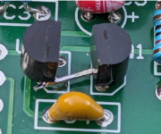
The fix amounted to this simple haywire. For those only following this thread, I wrote up the details in here.

1714923212644.png
 
Back
Top