• Please review our updated Terms and Rules here

IMSAI newbie, no idea what I'm looking at

Dokken

Experienced Member
Joined
Feb 27, 2018
Messages
249
Location
TN
I've had the case and panel for an IMSAI for a while and I just put together a CPU repro board from tindie. the front panel had some bad logic chips and a couple of troublesome switches, the CPU is untested since being assemble by me, and I need help understanding where I stand.

I have another S100 machine that I really haven't gotten into, so I have a few cards to use. I have inserted a Compupro RAM 17 with switch 1 set to 1-9 on, 10 off (1 is front panel control). switch 2 is currently set to 1 on, all others off.

with the RAM 17 installed, I had very limited control until I taped off pin 20 on the RAM card per some info I found here:
do I also need to tape off pin 70?

here's what it does as of now. Can anyone advise me where I stand from this?
 
The alternating, all ones and zeros on alternating addresses is typical of many RAMs.
Bit 2 looks to have some cross talk some place. If I saw things right, it was able to go to 0 in some cases of address.
Cross talk of this sort could be data of address. At his point you haven't run enough experiments to make any judgement as to possible cause.
Common place for cross talk is the main bus board.
Dwight
 
Thank you, Dwight, and Merry Christmas to all.

Can you guide me through some tests? I'm trying to understand the functionality and status.
 
First off, have you read the manual and tried to enter a simple series of byte values into the memory and then checked to see whether they read back correctly?

If the machine doesn't do that correctly, we need to find out why.

If that checks out OK, we can enter a simple program and test further.

Dave
 
Thanks, Dave. It seems like the only time we chat is when I have computer problems. ;-)

I am not able to enter the test program 1. data LED 2 (third from right, top right row) seems stuck on and does not switch. I have checked the physical switch with a meter and it does work properly.

also, I have the IMSAI replica panel from high nibble so I'm able to simulate the test program 1 on there and it, of course, works.

but it seems I'm stuck with not being able to switch bit 2 of for deposit. the LED for data 2 does work, as it will change during reset, etc. but during examine it is always stuck on.

any ideas what this would suggest?
 
I find using an ROM emulator or burner more convenient than using a front panel for fixing systems.
With it I write small test code snippets to show signs of life like lighting a output LED/Selecting a disk drive or to toggle some RS232 output pins.
From that I then load the ROM emulator with memory tests.
 
>>> any ideas what this would suggest?

I'll dig the schematics out and have a look. The first thing to do is to make sure that the front panel works.

We ought to strip the machine down to the bare minimum. I will work out for you what that is. The less we have in the machine, the better...

Dave
 
Merry Christmas, all.

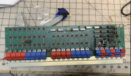
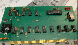
While it's on my mind, here's some info on the CP-A I have. I've owned this for a long time but never tried it until recently when I built the 8080 CPU reproduction board.

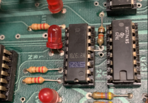
CP-A is a REV-4 with no visible modifications, wires, etc EXCEPT for U24 pin5 which was bent out/floating. I'm not sure if this was intentional as I do not see this pin mentioned in any of the engineering change notices. when I disassembled, cleaned, and reassembled I fully inserted this chip.

also pictured is the 8080 repro card.

current testing is using the CP-A, 8080 CPU, RAM17. I've also tried with a Godbout active terminator card with no change.

have a great holiday!
 

Attachments

  • imsai u24 pin 5 Screenshot 2023-12-25 at 6.26.09 AM.png
    imsai u24 pin 5 Screenshot 2023-12-25 at 6.26.09 AM.png
    4.8 MB · Views: 8
  • imsai cpa Screenshot 2023-12-25 at 6.25.07 AM.png
    imsai cpa Screenshot 2023-12-25 at 6.25.07 AM.png
    3.9 MB · Views: 8
  • imsai 8080 cpu repro Screenshot 2023-12-25 at 6.24.16 AM.png
    imsai 8080 cpu repro Screenshot 2023-12-25 at 6.24.16 AM.png
    3.9 MB · Views: 8
Merry Christmas.

I am looking at your issue now.

The documentation on the RAM17 board clearly indicates to isolate S-100 bus pins 20 and 70.

A quick look at the IMSAI CPA schematic shows that pin 70 is connected to GND anyhow but pin 20 IS used.

Pin 20 should be HIGH. If you plug an unmodified IEEE-696 memory board in it will pull this signal LOW and really mess up the control panel.

I see you have isolated pin 20, but are asking the question about pin 70. I would have isolated pin 70 myself, but (from what I can see) this wouldn't have any effect (I don't think) on the operation.

Thanks for providing the EXACT part numbers of what you have. That was going to be my next question...

I will checkout that pin next you bent back in.

I will also checkout your video again also.

Dave
 
U24 pin 5 (that I assume is a 8T97) SHOULD be inserted into the socket.

This pin is the memory write (MWRITE) signal. If this pin is not inserted, the memory will not be written to by the front panel.

EDIT: I see from your photographs that U24 is an 8T97. Also, the bend on pin 5 doesn't look intentional! I suspect it got bent when the previous owner inserted the IC...

Dave
 
Last edited:
First off I would check the continuity of ALL of the address switches with the power OFF using the resistance setting of your multimeter.

Turn them ON and OFF and make sure the resistance changes from very LOW to very HIGH.

Look for differences in the operation of the switches on bit 2 and bit 9 (counting from 0) as these two bits appear to be 'problematic'.

Do you have a logic probe?

Dave
I do have a logic probe.
 
Thank you again, Dave. I will break away this afternoon and try to give the switches a proper test. I had trouble with basic continuity early on, so I would not rule out temperamental physical switches. I'll measure/log resistance.

they are unique stubby toggles, and if I determine bad ones I can temporarily wire in a replacement toggles I have....just want to be gentle with the board.
 
… I've also tried with a Godbout active terminator card with no change. …
Terminators (passive or active) are used at the ends of signal traces for dynamic signal integrity by attenuating any signal reflections caused at the ENDs of signal traces. Usually they are only needed when the signal trace lengths exceed the TEL (transition electrical length) for the signals used. For TTL it is 60 feet & for ASTTL it is 1 foot.
Eric Bogatin, Lee Ritchey, Bruce Archambeaul, Henry Ott and others have some wonderful books and presentations on the subject.
 
Christmas Day stuff, I'll have some time being off from work this week and will get the switches verified.
 
Last edited:
Just a thought. To start you should be able to test some output signals of your Front Panel with no cards installed. e.g. read and write signals.
Then progress to just a memory card in place. For ROM you should be able to read its contents and for RAM you should be able to read and write values.
 
In a basic IMSAI there is no ROM of course.

If you start to put too many unknown cards into a system, you don't know where you stand.

The basic system is a CPU, RAM and front panel.

The system is 'almost' working. It just appears to be the odd address switch (one in the high byte and one in the low byte) - or the associated 7406 driver - or PCB wiring / soldering that appears to be in error (until we know more if course).

Dave
 
Back
Top